

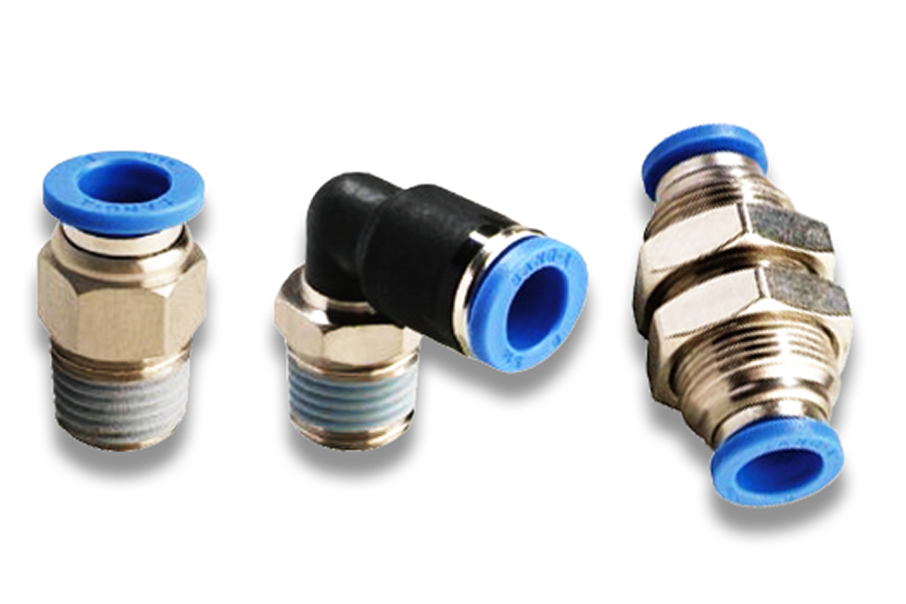
O) is the default — sets cylinder speed by throttling the exhaust air. The most common attach miss on the cylinder quote. DISTRIBUTOR-FIRST SUPPLY PARTNER · SINCE 1999 Live · Pneumatic Automation System
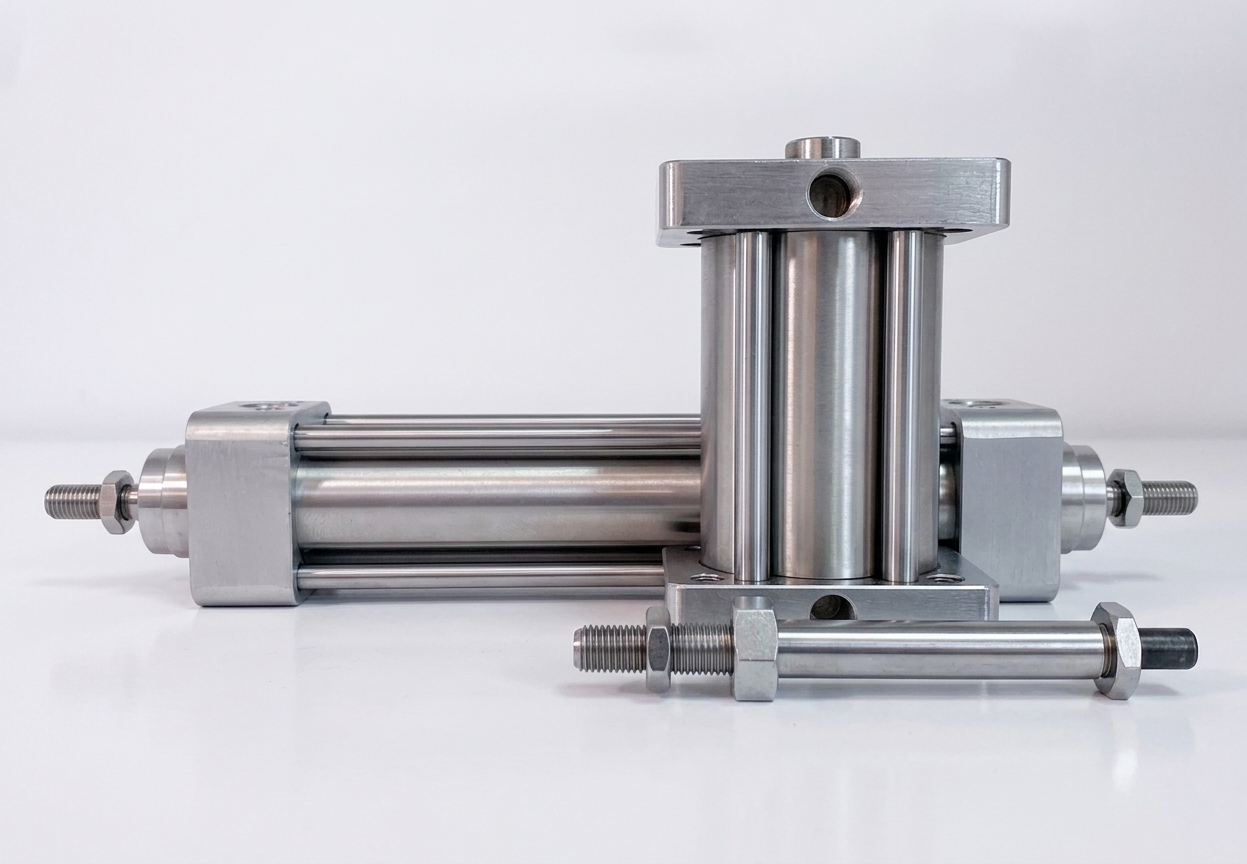
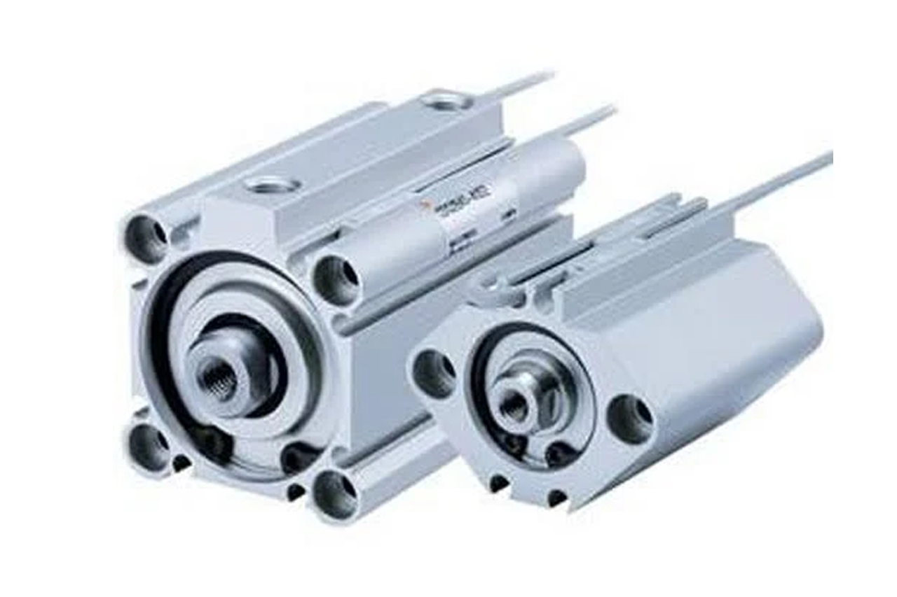
An ISO 15552 cylinder (the European/metric dimensional standard for profile cylinders) is a pneumatic actuator with an extruded aluminum barrel, a built-in longitudinal slot for magnetic position switches, and mounting dimensions fixed by the ISO 15552 standard. It is the default linear actuator on modern OEM automation in the 32-100mm bore range — pick-and-place arms, conveyor diverters, clamp stations, lift platforms, indexing tables. The cylinder mounts to the machine frame via foot, flange, pivot/clevis, or trunnion hardware (all to the ISO 15552 accessory standard, so brackets cross brands) and drives a load through its rod end.
Tips and pointers on when ISO 15552 is the right linear actuator — and when to spec a different cylinder family. Scroll the strip →
Bore, stroke, mount geometry, and rod-end thread are all fixed by the ISO 15552 standard — any compliant brand swaps into another's mount without re-engineering. One spec, three tiers at three price points on every quote.
A longitudinal slot in the barrel extrusion accepts magnetic switches with no external bracket. Slide in, set with the cylinder cycling, tighten. The PLC gets extend-confirmed and retract-confirmed without a fabrication project.
Extruded aluminum barrel, chrome rod, NBR seals, adjustable air cushion both ends, magnetic piston standard. 50M+ cycles on Industry Leader tier, 10-25M on Emerging tier — the dominant new-build cylinder in modern packaging, assembly, and material handling.
Push force = pressure × piston area. At 80 PSI: 50mm ≈ 245 lbs, 80mm ≈ 625 lbs, 100mm ≈ 975 lbs. Add 25-50% safety factor. Every cylinder sale is also 2 speed controllers + 2 position sensors + a rebuild kit — capture them on the same line.
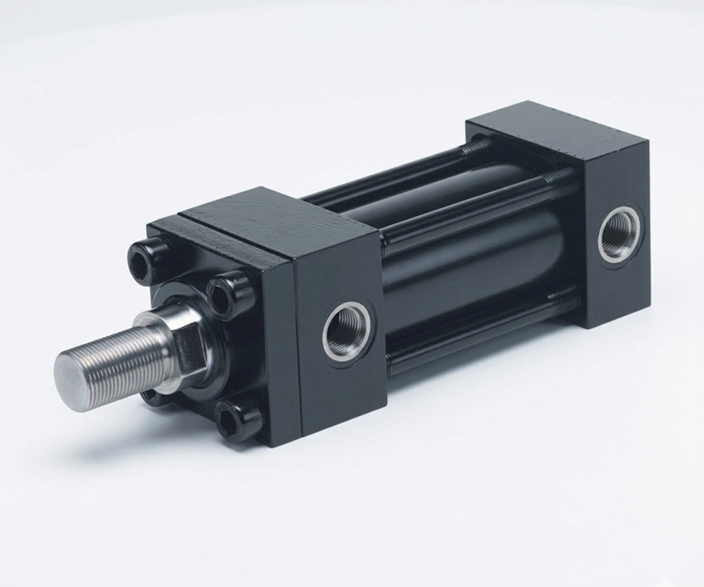
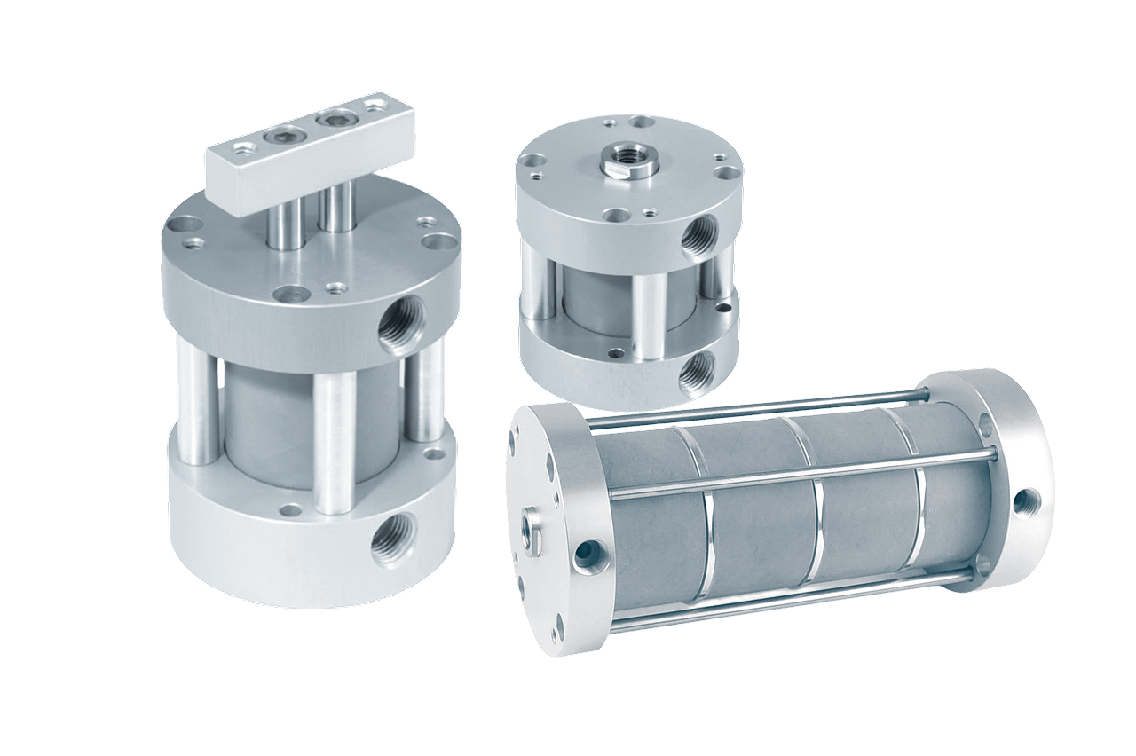
Above ~100mm (4") bore or on press / forming / stamping work, the tie-rod construction is the right answer. → Switch to NFPA tie-rod for 1.5"-14" bore, shock loads, and field-rebuildability on installed-base machines.
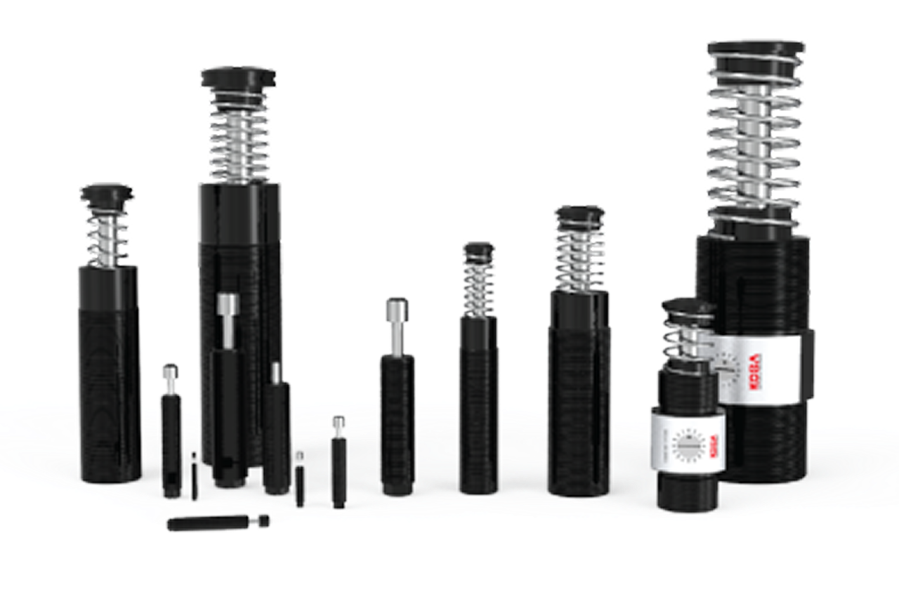
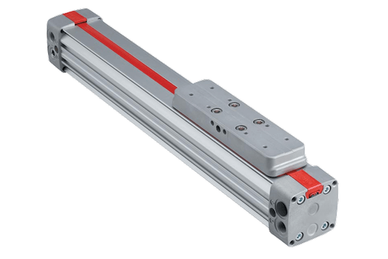
A 1m ISO 15552 needs 2m of installed length — the body has to hold the retracted rod plus a full stroke to extend it. → Re-spec to rodless: external carriage rides the barrel, installed length ≈ stroke length.
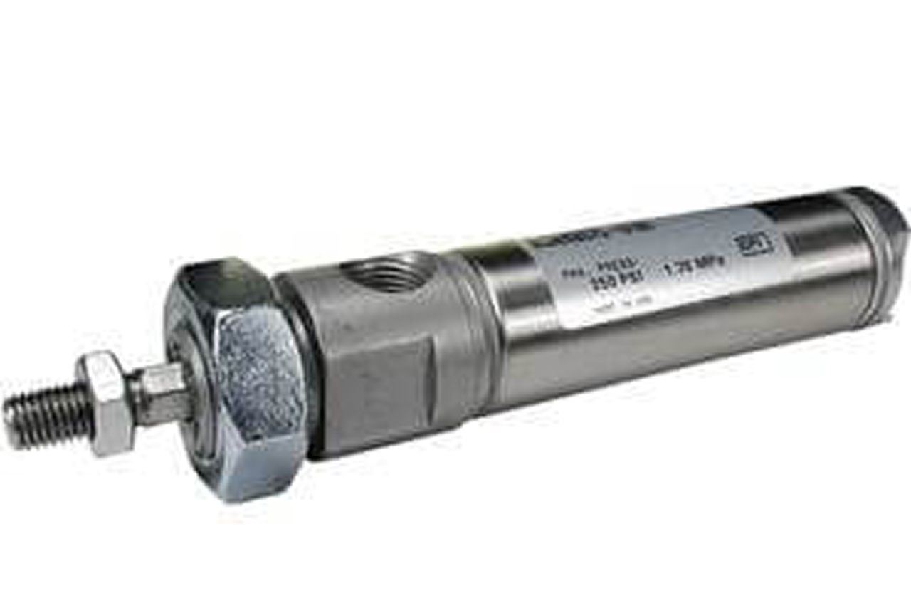
Standard ISO 15552 in foundry heat, cement dust, or 2-5× shock loading fails at 1/4 to 1/2 service life. → Re-spec to heavy-duty cast with FKM seals and hard-chrome rod when the environment, not the motion, drives the spec.
From the machine spec sheet → to the part number. Answer what you know — leave the rest blank — and send.
Most distributors sell one brand per product type. SPC's 60-brand portfolio means every Product Type page surfaces three real options matched to how your customer is buying today. Pick the tier; the quote desk handles the cross-reference.
ISO 15552 is the sale that turns one quote into a 10-year MRO line.
Each industry below uses this product across the listed areas. Open an industry to see how it fits the rest of its system.
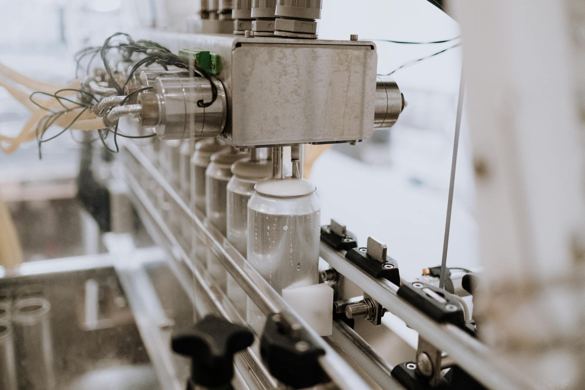 Food & Beverage Processing →
  Pharmaceutical, Medical Device & Laboratory →
 Also applies to OEM automation — general-purpose mid-bore actuation · Replacement on legacy machines · Hazardous-location equipment · Test stands & lab equipment · Robotic auxiliary axes & pneumatic clamps
Every entry is a real product on this site — linked, not just named. Quote them on the same line item.
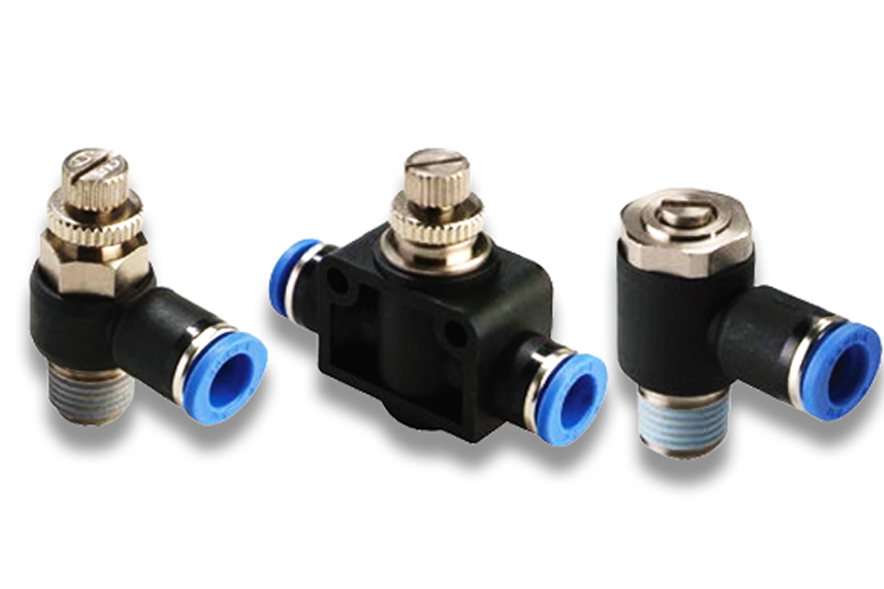
O) is the default — sets cylinder speed by throttling the exhaust air. The most common attach miss on the cylinder quote.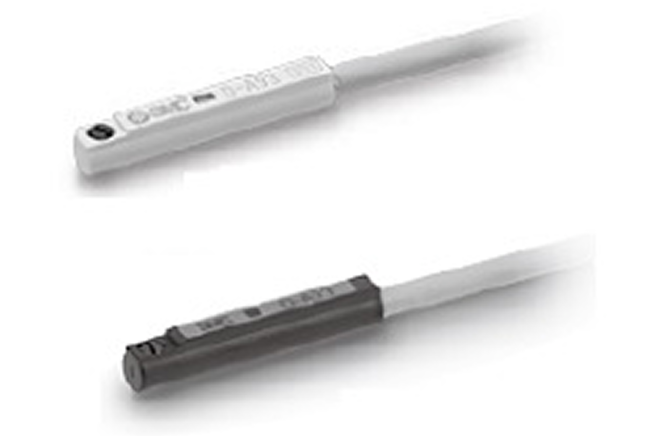
Stock the rebuild-kit + 2 position sensors + 2 speed controllers on the customer's MRO shelf at original cylinder sale. Three-year forward inventory pays for itself the first time the cylinder needs service — kit + sensors + controllers on the shelf turns a 3-day production downtime into a 30-minute rebuild.
Send us the application — a specialist routes you to the correct tier with a configured part. Lead-times and pricing returned within one business day.
—. We reply within one business day with pricing, lead-time, and configured parts.