DISTRIBUTOR-FIRST SUPPLY PARTNER · SINCE 1999 Live · Pneumatic Automation System
SPC Company
Pneumatic Automation / Sensing & Feedback / Sensors & Switches / Cylinder Position Sensor
Layer 06 · Sensing & Feedback Industry Leader · SMC
01What it is

Cylinder Position Sensor

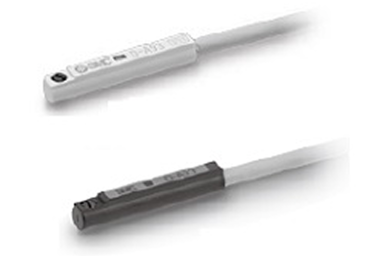
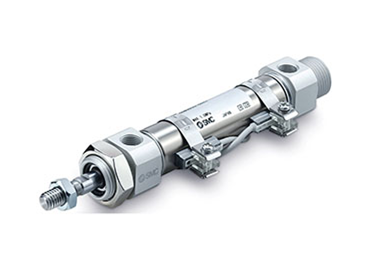
A cylinder position sensor — also called an auto-switch — detects the magnetic piston inside a pneumatic cylinder and tells the control system where the rod is. It confirms that the cylinder has actually reached end-of-stroke, extended or retracted, before the machine's logic advances to the next step. Without that confirmation the PLC is working blind: it commands a motion and assumes it happened. With it, the sequence is verified at every step. The sensor mounts on the outside of the cylinder body and reads the piston's magnet straight through the barrel wall — no port, no air connection, no break in the pressure envelope. It is a purely electrical add-on. Two sensing technologies are used: a reed switch (magnetically actuated mechanical contact, simple and low cost, suited to lower-cycle duty) and a solid-state switch (magneto-electronic element with no moving contact, faster and far longer-lived, correct for high-cycle automation and safety-critical motion).

Real-world reference Representative cylinder position sensor
Cylinder Position Sensor — representative product photo
02Why it's needed

Why this matters.

Tips and pointers on when and how to spec cylinder position sensors — and when to step up technology or sealing. Scroll the strip →

01 · Key point
Closes the PLC's blind loop.

Without end-of-stroke confirmation, the PLC commands extend and waits a fixed time hoping it happened — until the cycle slows from low supply, a clogged muffler, or rod interference, and the next step fires on nothing. The sensor gives electrical certainty before the sequence advances.

02 · Key point
Purely electrical add-on.

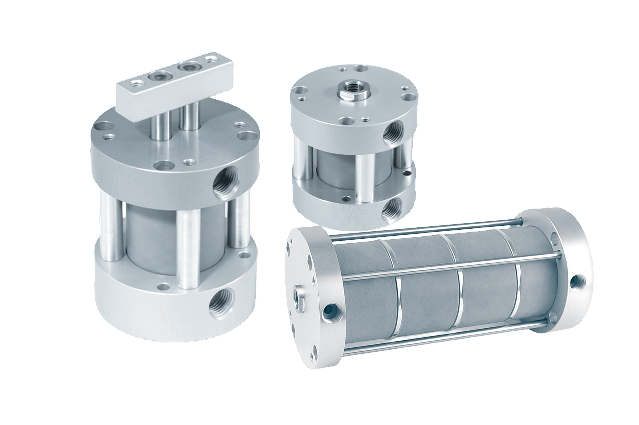
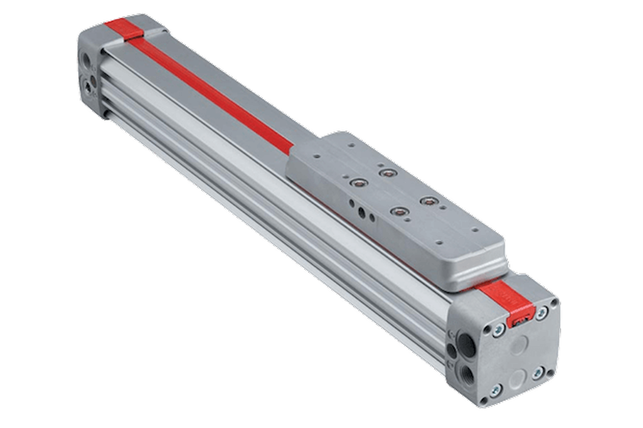
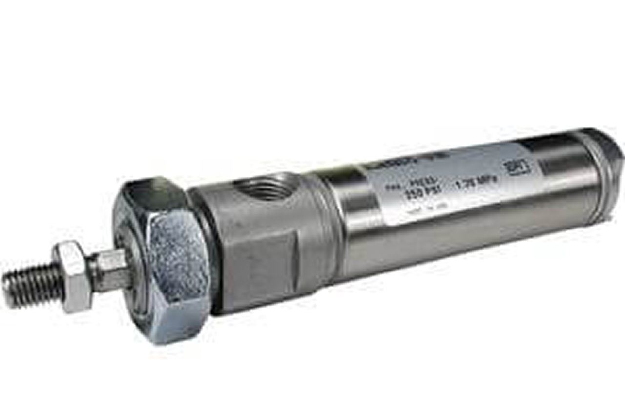
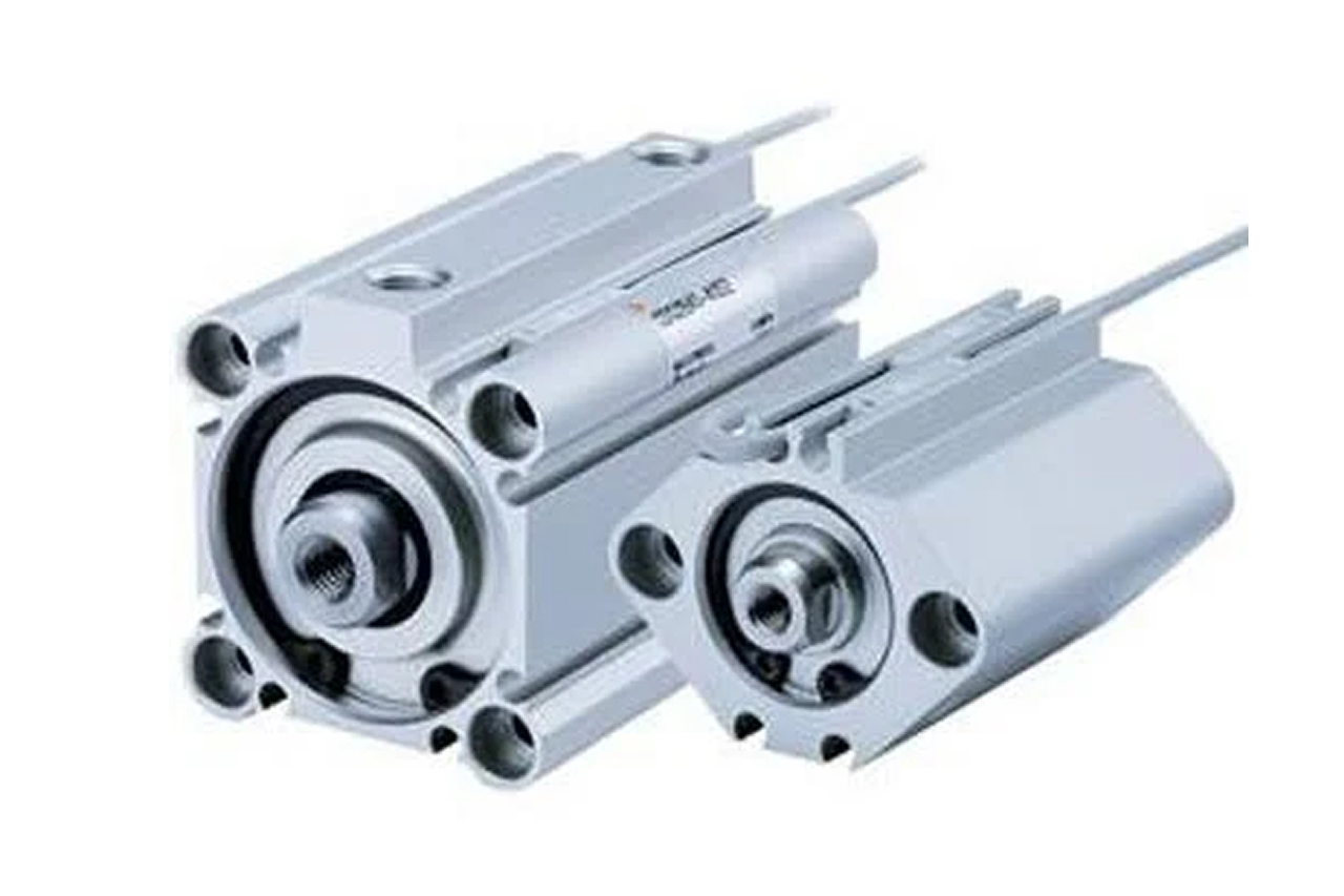
No air connection, no port, no break in the pressure envelope. Sensor reads the cylinder's piston magnet straight through the barrel wall — slides into the ISO 15552 slot, clamps to an NFPA band, threads into a compact body, or rails on rodless. Mounts in seconds, no fabrication.

03 · Key point
Highest-volume reorder line.

2 per cylinder is standard (extend + retract). Math: cylinder count × 2 + 20% spare. A 50-cylinder plant generates 5-10 sensor replacements/year — water ingress on washdown, cable damage on moving installs, drift after years of vibration. Capture install count at original sale.

04 · Pro tip
Match output to the PLC input.

Sensor selection is series-specific (mount must match cylinder family), but the call that breaks at install is electrical: 3-wire PNP (most North American), 3-wire NPN (legacy / European), or 2-wire. Pull the PLC input card spec sheet before quoting; get NO vs. NC right for safety circuits.

05 · Where not to use
Reed switches in 24/7 production.

Reed switches use a mechanical contact — reach end-of-life within 1-2 years on a 50-cylinder line running continuous. → Switch to solid-state (Hall-effect / magnetoresistive) for 10-20× service life; cost premium pays back in months on production rates.

06 · Where not to use
Standard sensors in washdown.

Standard sensors aren't sealed for direct washdown spray — water tracks down the cable, ingresses through the housing, fails within months. → Re-spec to IP67-rated sealed variants with stainless mounts and sealed cable entry for food, pharma, and outdoor installs.

07 · Where not to use
Standard sensors in foundry heat.

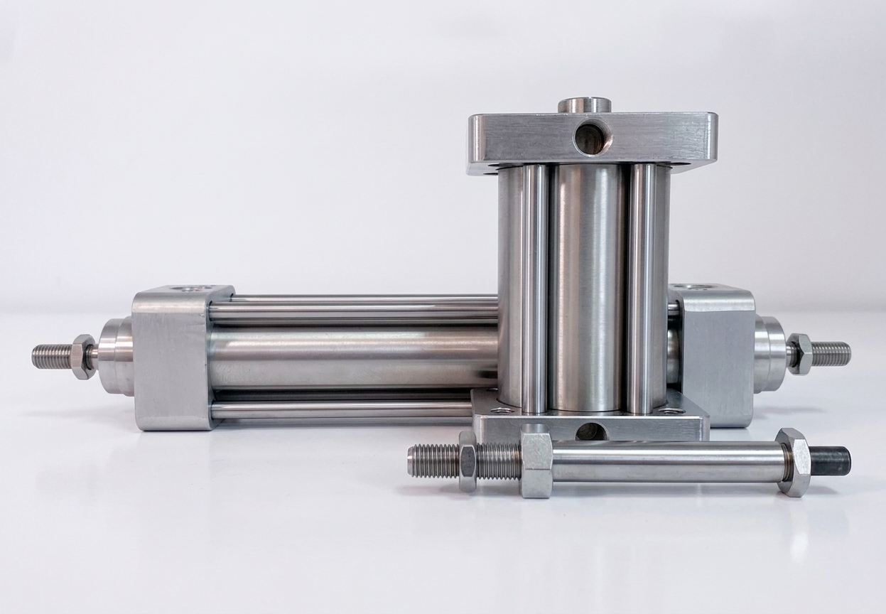
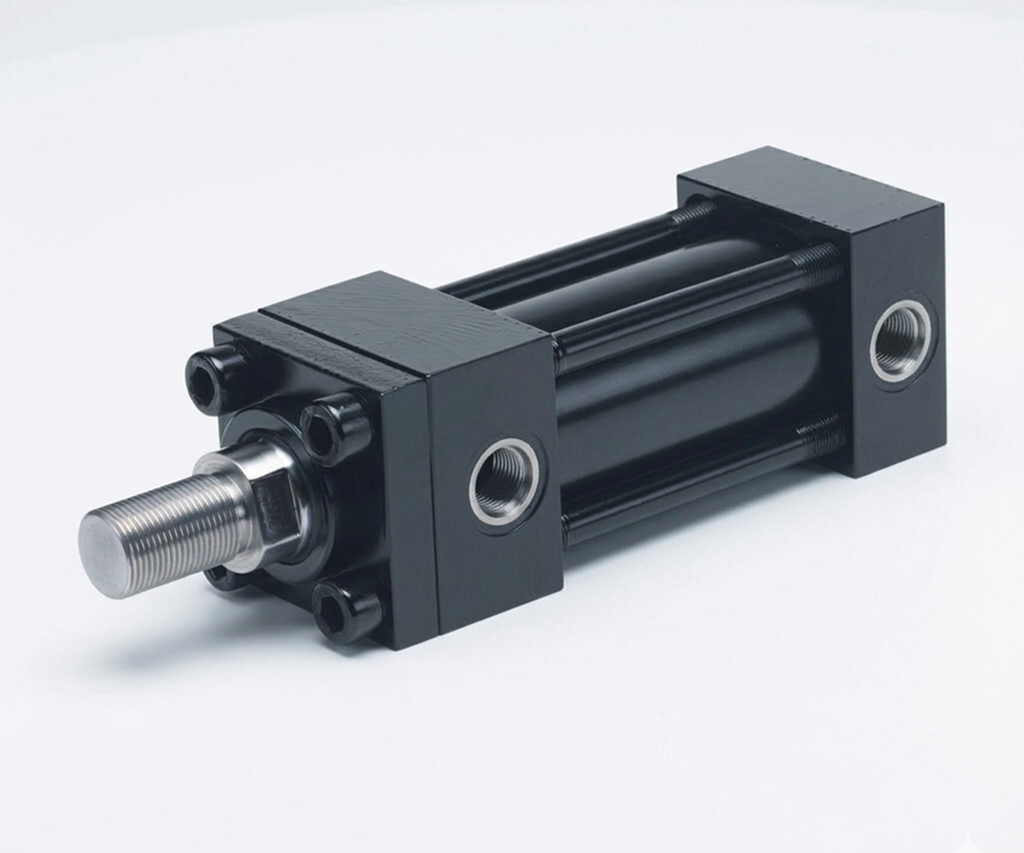
Most switches are rated to ~70°C max — fail fast above that in oven, heat-treat, or near hot-process zones. → Switch to high-temperature variants rated 80-100°C continuous for severe-service installs paired with heavy-duty cast cylinders.

03Key selection criteria

What we need to spec it right.

From the machine spec sheet → to the part number. Answer what you know — leave the rest blank — and send.

01 · Input
Sensors are selected to the cylinder series, not chosen independently — the mount geometry and piston magnet match a specific family. Read the cylinder nameplate before quoting.
SMC · AIGNEP · Parker · Bimba · Festo
02 · Input
Inspect the cylinder body — different families use different sensor geometries. Mount must match.
ISO 15552 groove (longitudinal slot, T-slot on profile) · NFPA band (tie-rod, round-body) · Body-integrated (compact / dedicated non-rotating) · Rail-mount (rodless)
03 · Input
Set by duty cycle. 24/7 production usually demands solid-state; reed contacts wear out fast in high-cycle service.
Reed (mechanical contact — lower-cycle, cost-sensitive) · Solid-state (Hall-effect / magnetoresistive — high-cycle, safety-critical, 10–20× life)
04 · Input
Match to the PLC input card — get the card spec sheet before quoting. Normally-closed is for safety-circuit applications.
3-wire PNP (sources current — North American standard) · 3-wire NPN (sinks current — legacy / European) · 2-wire (simpler, less robust) · NO or NC contact
05 · Input
Pulled from the control logic. Two per cylinder is the standard (extend AND retract); mid-stroke adds on long-stroke or multi-position applications.
One end of stroke · Both ends (extend + retract) · Mid-stroke (multi-position / rodless)
06 · Input
IO-Link is a digital network protocol that runs over the 3-wire sensor cable — sensor reports digitally on a smart valve terminal's network instead of a discrete PLC input. Ask about the network scope.
Standard discrete · IO-Link (smart-terminal architecture)
07 · Input
Pre-wired for simple installs with known run length; connectorized lets the cable be swapped without disturbing the sensor mount — preferred on moving / high-vibration installs.
Pre-wired: 1m · 2m · 3m · 5m · Connectorized: M8 · M12
08 · Input
Math is install-count-driven: 2 per cylinder (extend + retract) + 20% spare. A 50-cylinder plant generates 5–10 replacements/year from washdown ingress, cable damage, drift.
1 per stroke end · 2 per cylinder (standard) · Kits per machine (10/25 packs for MRO crib)

Need different sizes, colors, or quantities? Fill the form, add to quote, then fill again — each click is one quote line.

04Choose your solution tier  ·  core differentiator

Whatever your lever — spec, value, or price — SPC has the right brand.

Most distributors sell one brand per product type. SPC's 60-brand portfolio means every Product Type page surfaces three real options matched to how your customer is buying today. Pick the tier; the quote desk handles the cross-reference.

05How to sell this  ·  distributor talk track

The tier conversation closes the deal. The cross-reference catalog wins the next one.

Position sensors are 2-per-cylinder. Count the cylinders, multiply by 2, add 20% for spares. The recurring line runs itself.
The SPC difference · how distributors actually buy

The 30-second positioning

Position sensor quoting is high-volume MRO work that pairs naturally with cylinder sales. Every modern automation-grade cylinder needs at least one sensor (end-of-stroke confirmation) and usually two (extend AND retract); some applications add mid-stroke sensors. Math: cylinder count × 2 + 20% spare = total sensor quantity. Capture that count into the MRO system at original cylinder sale, and the reorder line runs predictably as switches age and fail across the installed fleet.

Confirm sensor compatibility with the cylinder series first. Sensors are matched to specific mounting profiles (ISO 15552 slot, NFPA band, compact integrated, dedicated non-rotating body-mount, rodless rail-mount). Always tie the sensor spec to the cylinder it's mounting on — reading a sensor catalog without the cylinder series is incomplete.

Reed vs. solid-state by duty. Solid-state for high-cycle production, safety-critical motion, and service-route customers. Reed for light-cycle prototype, cost-sensitive work, or secondary-signal duty. The cost premium for solid-state pays for itself in service life on production applications.

Match electrical output to PLC input. 3-wire PNP (most common in North America), 3-wire NPN (some legacy / European), 2-wire (simpler, less robust). NO or NC contact per the safety-circuit logic. Get the PLC input card spec sheet before specifying.

Specify cable vs. connector. Pre-wired cable (1m, 2m, 3m, 5m) for simple installs. M8 / M12 connectorized for moving installs where cable replacement is likely — lets the cable swap without disturbing the sensor mount.

Tier: Industry Leader tier is the OEM-default on most modern pneumatic automation. Full lineup across reed and solid-state, all standard output types, all standard cable/connector options, all standard mounts. Cross-mount versions cover all major cylinder brands. Value tier is acceptable on prototype / non-critical; on high-cycle production, trigger consistency and cable durability variance on cheaper sensors costs more in service calls than the premium-tier price difference.

Recurring revenue is in the replacement cadence. Sensors are the most common failure item in the cylinder ecosystem — water ingress on washdown installs (2-4 years), cable damage on moving installs, trigger drift after years of vibration, end of service life on reed switches in high-cycle service (1-2 years). A 50-cylinder plant generates 5-10 sensor replacements per year. Capture install count and matched part numbers into MRO at original sale.

Customer cue → talk move

"Sensors for any cylinder brand"
Confirm the mounting profile (ISO 15552 slot, NFPA band, compact integrated, rodless rail-mount). Match reed/solid-state, PNP/NPN, cable/connector. Quote at least 2 per cylinder.
"Sensors for non-Industry-Leader cylinders"
Cross-mount variants cover most major cylinder brands; verify profile compatibility.
"High-cycle line, sensors failing fast"
Customer is running reed in high-cycle service. Switch to solid-state for 10-20x service life improvement. Cost premium pays for itself within months on production rates.
"Sensor not triggering or triggering intermittently"
Drift, water ingress, or cable damage. Stock spares.
"IO-Link compatible sensors"
IO-Link variants from the matched sensor family. Standard on IO-Link-architected automation.
"Multi-position / mid-stroke detection"
Multiple sensors along the body, solid-state preferred for precise trigger consistency.
"Washdown environment, sensors corroding"
IP67-rated sealed variants. Stainless mounts; sealed cable entry.
"New machine build, sensors not yet spec'd"
2 per cylinder is standard; quote with the cylinder order to avoid emergency commissioning orders.
06Where it's used

Industries served.

Each industry below uses this product across the listed areas. Open an industry to see how it fits the rest of its system.

Also applies to End-of-stroke confirmation on every PLC-controlled cylinder · Safety-critical motion verification · Solid-state with safety-rated output · Multi-position sensing on long-stroke cylinders · IO-Link integration for smart automation · Replacement on aging installs · The recurring MRO line. · Mixed-cylinder fleets with consistent sensor standard · Production-line cycle-rate monitoring · IP67-rated sealed variants

09Install · 5 critical steps

The things that matter on the first install.

Step 01
Match the sensor to the cylinder's mounting profile
ISO 15552 longitudinal slot, NFPA clamp-on band, compact integrated mount, dedicated non-rotating body-mount, rodless rail-mount. The sensor must match the cylinder series's mount geometry; cross-mounting is sometimes possible with cross-mount variants but verify compatibility before ordering.
Step 03
Match electrical output to PLC input
3-wire PNP (sources current to PLC input — most common in North America), 3-wire NPN (sinks current — some legacy and European installations), 2-wire (simpler wiring, less robust). Normally-open (contact closes on magnet detection — standard) or normally-closed (contact opens on detection — safety-circuit applications). Get the PLC input card spec sheet before specifying.
Step 05
Mount the sensor in the cylinder's groove or band
ISO 15552: slide into the longitudinal slot, position approximately at end of stroke, finger-tight the clamp. NFPA: install the band around the body, position the sensor under the band, tighten band clamp. Compact / MB: thread into integrated mounting position. Rodless: rail-mount on the cylinder's switch rail.
Step 06
Set sensor position by cycling, not by measurement
With the cylinder cycling at production speed and the PLC observing the sensor LED, adjust sensor position until the LED triggers reliably at the desired position. Slow-cycle adjustment misses the high-speed trigger point; static positioning misses entirely. Sensor LED is the visible indicator that the piston magnet is in the trigger range. Tighten the mount after setting position; re-cycle to confirm.
Step 07
Wire to PLC per the input card requirement
3-wire: brown (+24V), blue (0V), black (signal to PLC input). 2-wire: two-conductor connection (polarity per sensor spec, usually marked). Verify wiring at the PLC: signal lead to input terminal, common to PLC common. Test sensor operation through PLC diagnostic before committing to production.
10Troubleshoot · top failures

Most returns trace to one of these causes.

Symptom
Most likely cause
Fix
Sensor not triggering or triggering inconsistently
Sensor has drifted out of trigger position (most common, especially on vibrating equipment), water has ingressed into the housing, cable damage between sensor and PLC, or — rarely — piston magnet weakened after 20M+ cycles.
Re-position the sensor while cycling at production speed and watching the LED. If position is correct but trigger is intermittent, inspect cable for damage; replace if found. For water ingress, the sensor is end-of-life — replace with IP67-rated variant if environment is wet. Magnet weakening means full cylinder replacement.
Sensor triggers continuously (always-on output)
Sensor failure (Hall-effect or magnetoresistive element failed, or reed contacts welded closed — yes, even solid-state can fail), wiring fault (signal lead shorted to power), or sensor magnetically saturated by a strong nearby magnetic field.
Disconnect sensor from PLC and test signal lead voltage with multimeter; if signal is always at full voltage, sensor is failed — replace. For wiring fault, inspect and re-wire. For magnetic saturation, identify and relocate the interference source.
Sensor LED flickers but PLC doesn't see the signal
PLC input card not recognizing the sensor's output (wrong PNP/NPN match, voltage incompatibility), wiring fault (signal lead disconnected, common not connected), or PLC programming not reading the input.
Verify PNP/NPN match between sensor and PLC input card. Check wiring continuity from sensor to PLC terminal. Test PLC input with a known-good sensor or force a signal at the PLC terminal to isolate where the signal is being lost.
Sensor triggers at the wrong stroke position
Sensor has physically drifted along the cylinder body (vibration over time, loose mount clamp), piston magnet has shifted internally (rare, on rebuilt cylinders), or — on multi-sensor installs — sensors swapped during a previous service.
Re-position the sensor to correct trigger location while cycling. Verify sensor identity (sometimes sensors get mislabeled during installs). On rebuilt cylinders, the piston magnet position should be unchanged from original; if shifted, the internal assembly is off and may need professional service.
Premature sensor failure on washdown or outdoor installs
Water ingress through cable entry or sensor body. Standard sensors are not rated for washdown — IP67 sealed variants are required for wet environments.
Replace with IP67-rated sealed variant. Verify cable routing protects against direct washdown spray; cable management with drain loops prevents water tracking down the cable to the sensor body. For chronic water-failure issues, the install environment may need additional protection (sensor cover, relocated to a drier position).
Reed switches failing in months on a new install
Cycle rate exceeding reed switch service life. Reed switches have mechanical contact life; high-cycle production (thousands of cycles per shift) reaches end of life within months.
Switch to solid-state. For existing reed installs on production machines, plan a replacement program at the next opportunity. Reed remains appropriate for light-cycle applications; production rate requires solid-state.

Get the right cylinder position sensor on quote in 24 hours.

Send us the application — a specialist routes you to the correct tier with a configured part. Lead-times and pricing returned within one business day.

Request a quote