DISTRIBUTOR-FIRST SUPPLY PARTNER · SINCE 1999 Live · Pneumatic Automation System
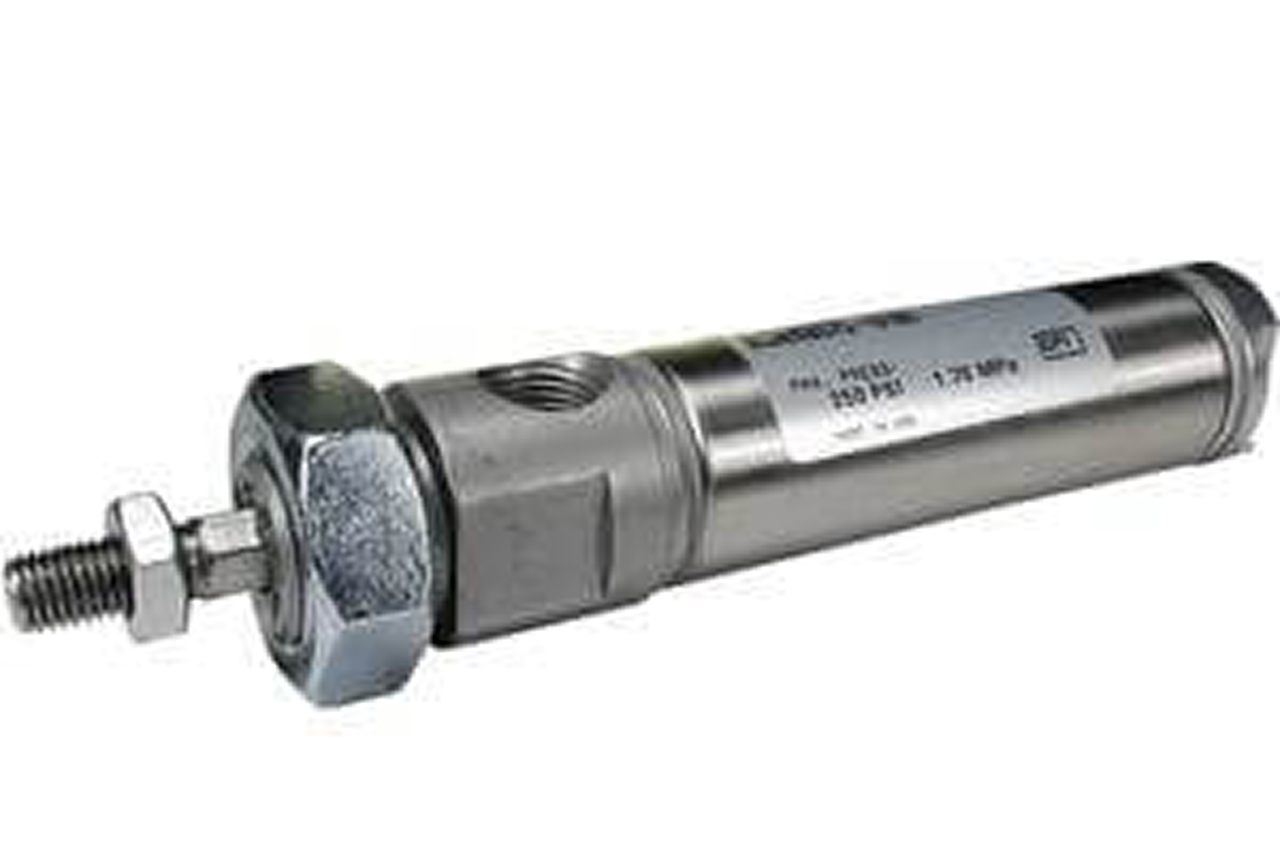
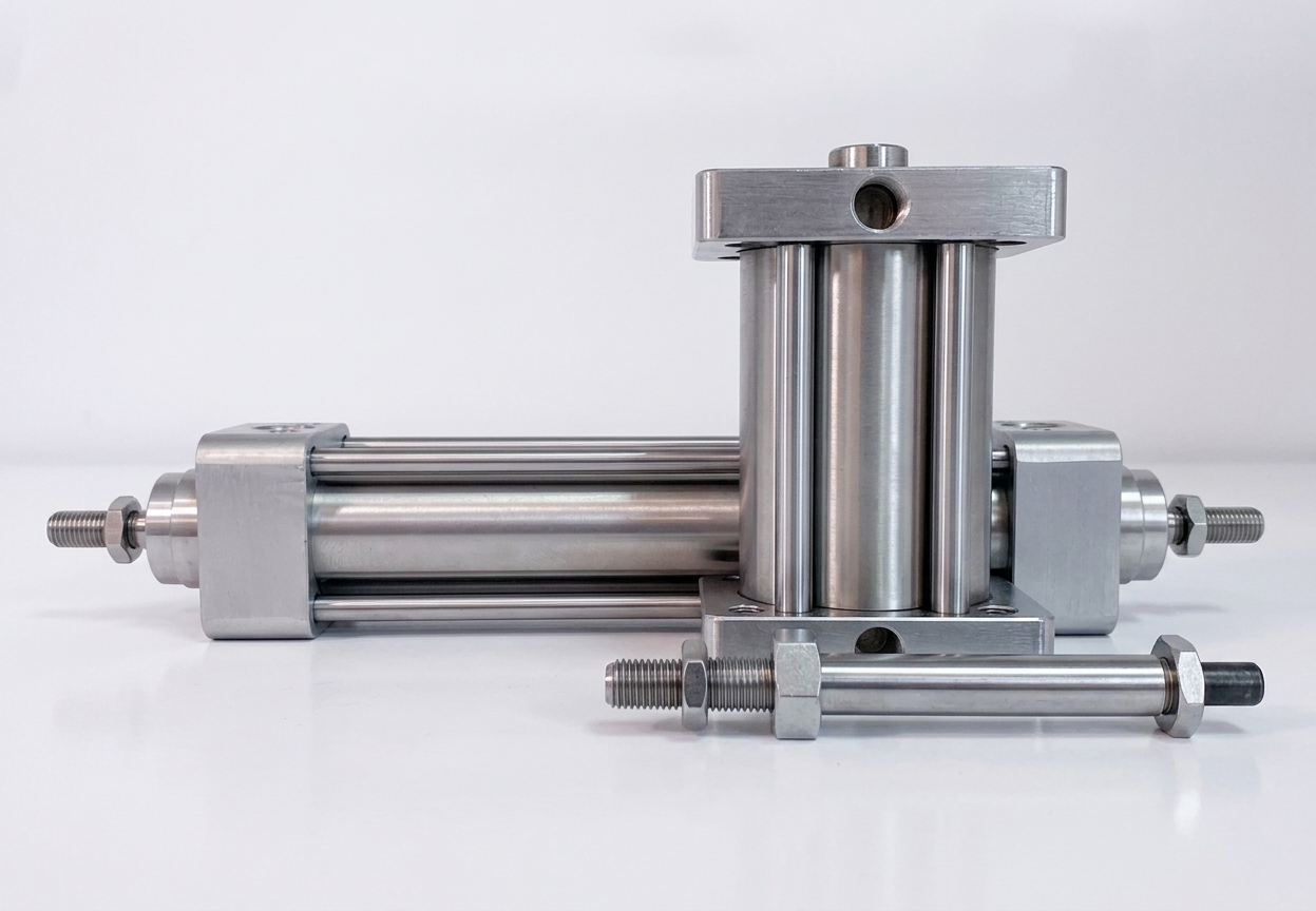
A non-rotating cylinder is a pneumatic cylinder built so the rod cannot twist about its own axis as it extends and retracts. An ordinary cylinder rod is free to rotate slightly, which is acceptable for a simple push but unacceptable when a tool, gripper, or workpiece on the rod end must keep a fixed angular orientation. The non-rotating design — typically a non-circular rod section or an internal anti-rotation feature — holds that orientation true through the full stroke. It is the right type for parts handling, pick-and-place, and any motion where the end-effector must not spin. It addresses rotation specifically; an application whose real problem is resisting side load or bending needs a guided cylinder, which adds bearing-supported guide rods rather than only constraining rotation.
Tips and pointers on when non-rotating is the right cylinder — and when the real answer is a guided cylinder or a standard variant. Scroll the strip →
A standard cylinder rod has 1-3° of rotational play — fine for a push, fatal for a vacuum cup, sensor, or gripper that must stay aimed at the workpiece. Non-rotating locks the rod's angle through the full stroke across millions of cycles.
Either a non-circular rod cross-section (D-shape, square, hex) riding in a matching end-cap bore, or an internal anti-rotation key (guide pin between piston and end cap) with a circular rod. The key-type accepts standard round rod-end hardware; non-circular needs matched hardware.
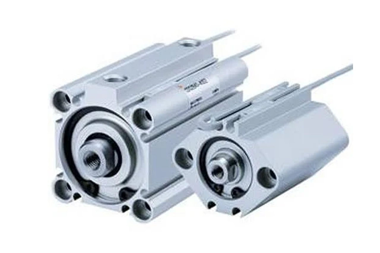
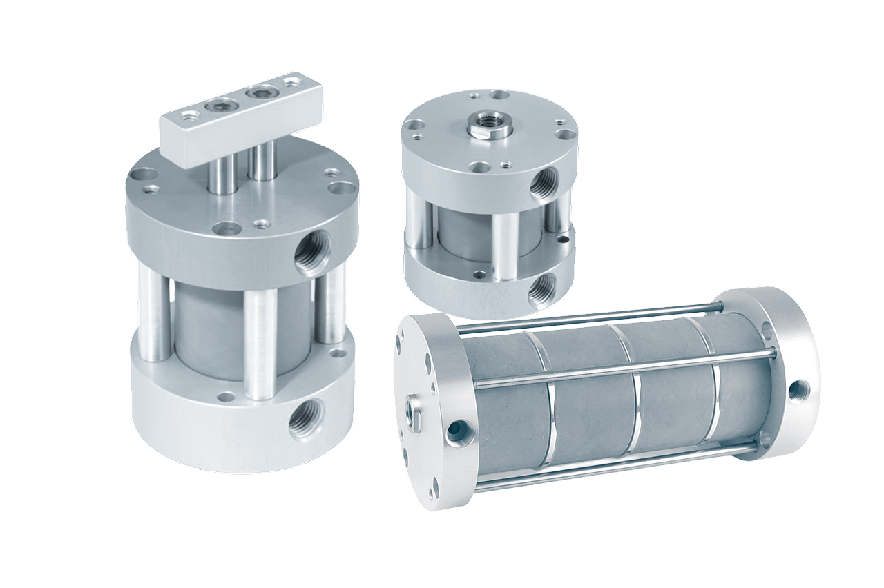
Configuration option on ISO 15552, NFPA, compact, and heavy-duty cast — plus a dedicated production-volume non-rotating series. Spec the family that matches the rest of the machine; non-rotating is an add-on, not a stand-alone universe.
The #1 misapplication is confusion with the guided cylinder. Ask first: "Orientation control of the end-effector (non-rotating), or side-load resistance on the rod (guided)?" Then match anti-rotation accuracy to the application — ±0.5° for vacuum-cup pickup, ±1-3° for gripper alignment.
Non-rotating constrains rotation only — rod-bearing surface is the same as a standard cylinder. Off-axis push, eccentric load, or guided motion wears the bearing within months. → Switch to a guided cylinder with external or internal bearing-supported guide rods that carry the load off the rod.
Standard cylinder rotational play doesn't matter when the rod is pushing a plate or clamping a fixture — non-rotating is over-spec'd and the non-circular rod-end hardware adds cost. → Re-spec to the standard variant (ISO 15552, NFPA, or compact) at the same bore.
Non-circular rod cross-sections (D, square, hex) reduce effective piston area vs. a round rod of the same nominal bore — naive force math comes up short. → Read actual push area from the catalog for non-circular designs, or pick an internal-key variant with full standard piston area.
From the machine spec sheet → to the part number. Answer what you know — leave the rest blank — and send.
Most distributors sell one brand per product type. SPC's 60-brand portfolio means every Product Type page surfaces three real options matched to how your customer is buying today. Pick the tier; the quote desk handles the cross-reference.
Non-rotating is the orientation-control cylinder, not the side-load cylinder. Qualify before quoting — customers asking for non-rotating sometimes need guided instead, and they'll be back next year with a worn-out cylinder if you skip the question.
Each industry below uses this product across the listed areas. Open an industry to see how it fits the rest of its system.
 Packaging & Printing →
  Material Handling & Conveyors →
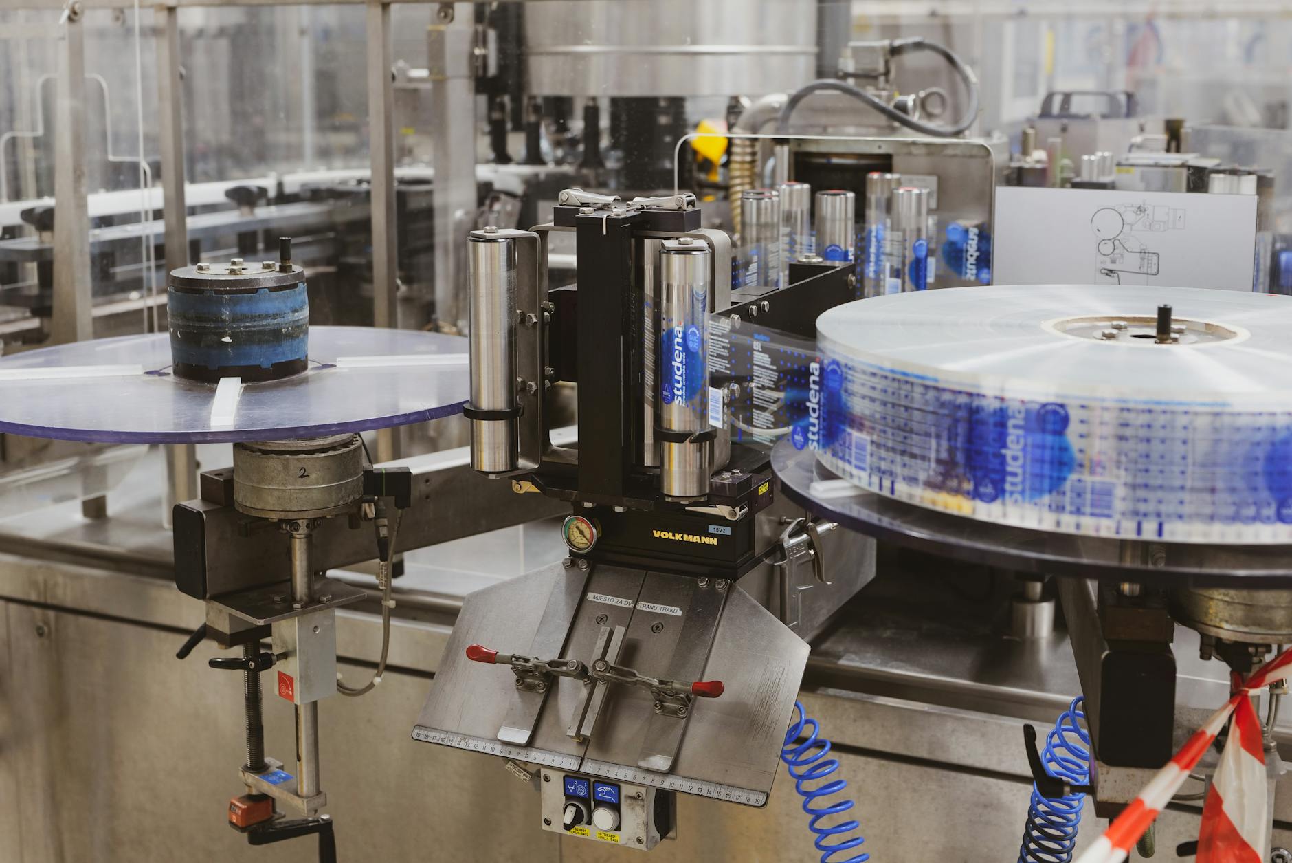
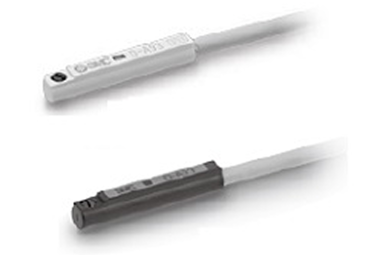
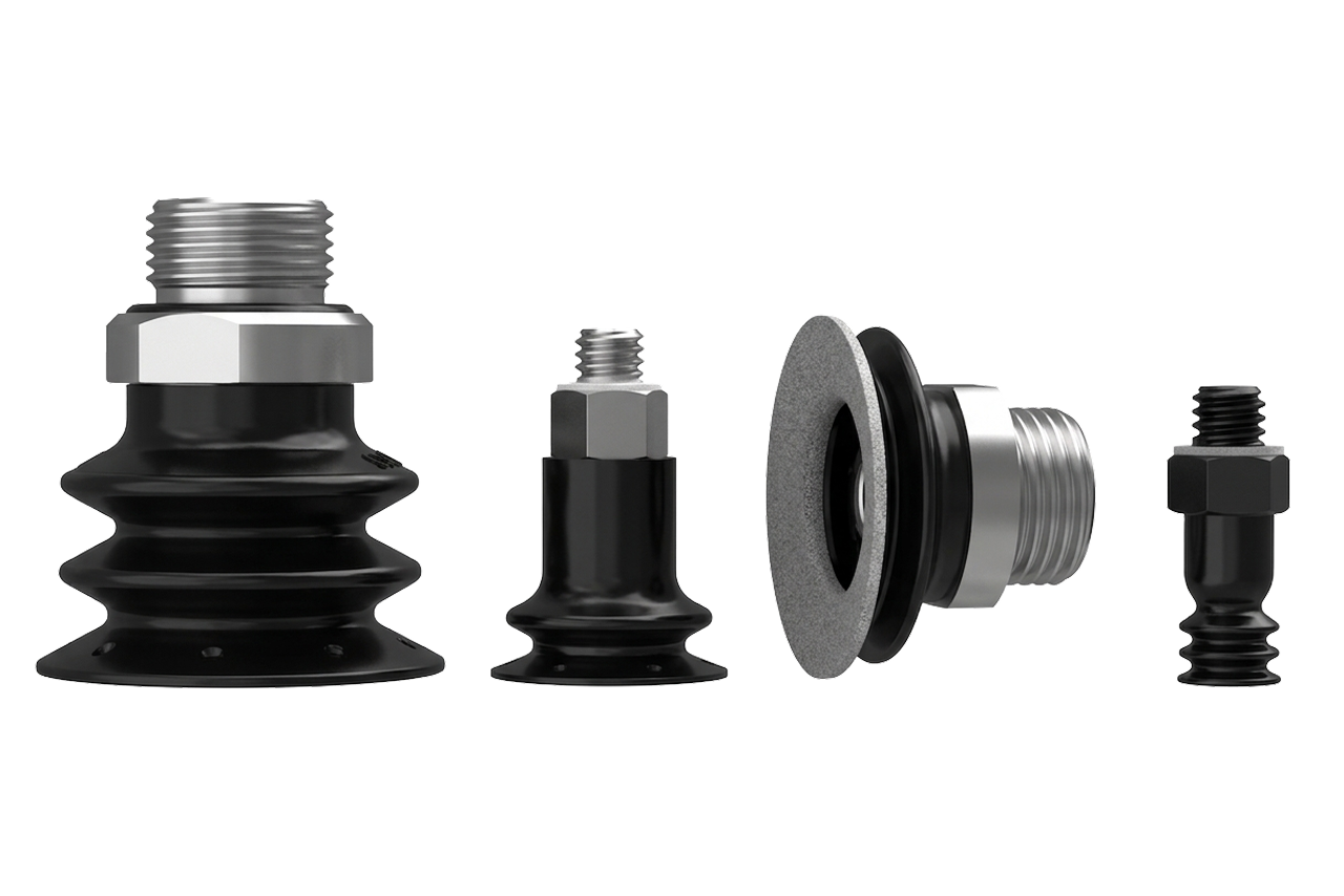
 Also applies to Vacuum-cup pick-and-place · tight anti-rotation accuracy (±0.5°) mandatory · Gripper alignment in robotic pick-and-place · Sensor placement and inspection equipment · Tool changers and tool positioners · Indexing pins with shaped (non-circular) ends · Custom machine builds with orientation-sensitive end-effectors
Every entry is a real product on this site — linked, not just named. Quote them on the same line item.
O) is the default — sets cylinder speed by throttling exhaust air. Critical on pick-and-place where end-of-stroke slam disrupts cup engagement.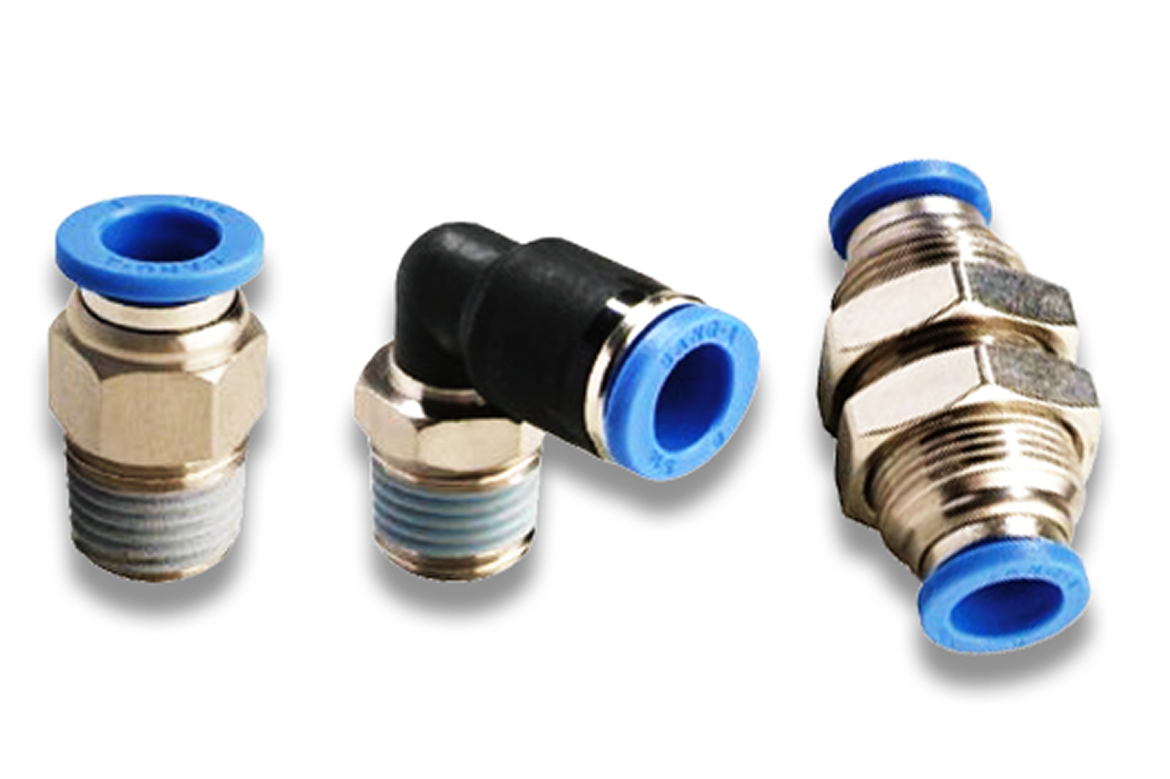
Stock non-rotating rebuild kit + 2 position sensors + vacuum-cup spares on the customer's MRO shelf for pick-and-place lines. Vacuum-cup wear runs faster than cylinder wear; cup replacement quantity is 3-5x cylinder quantity over the install's service life.
Send us the application — a specialist routes you to the correct tier with a configured part. Lead-times and pricing returned within one business day.
—. We reply within one business day with pricing, lead-time, and configured parts.