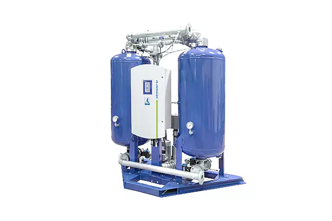
DISTRIBUTOR-FIRST SUPPLY PARTNER · SINCE 1999 Live · Compressed Air System
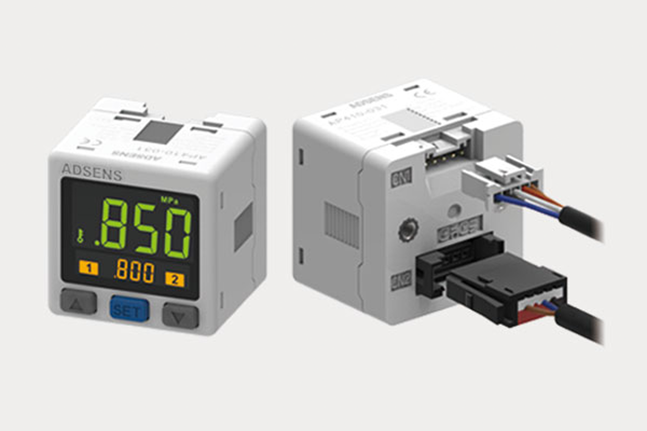
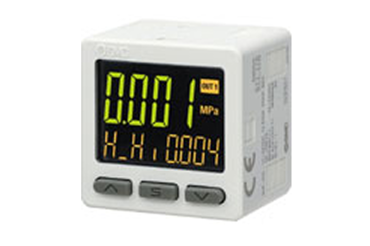
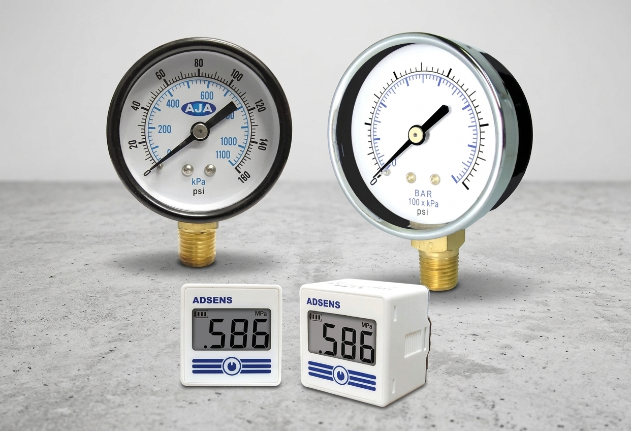
A pressure sensor reads what pressure a compressed air system is holding at a given point, or checks the differential pressure (the difference in pressure between upstream and downstream of a filter, used to indicate when an element is loading up and due for change) across a filter. It sits in the monitoring layer as the simplest of its instruments — the entry-tier product that answers a status question (is the system at setpoint, is a filter loaded, has the compressor cut out) rather than producing the audit-grade precision a logged historian needs. Two install patterns: single-point reading off the line (one tap), or differential check across a filter (two taps, one each side). Output is either a visual gauge an operator reads by eye, or an electrical signal (4-20 mA, Modbus, or IO-Link) to a controller.
Tips and pointers on when a pressure sensor is the right call — and when to spec something else. Scroll the strip →
Every PSI of avoidable drop across a loaded filter is ~0.5% of plant electricity. A pair of sensors across each coalescing stage (alarm at 8-10 PSI) recovers element cost in months — every multi-filter plant.
±1% of range for compressor-discharge control. ±0.5 PSI absolute for filter-differential alarms. ±0.25% with cal certificate for audit-grade. Match spec to job — over-spec wastes budget, under-spec produces wrong decisions.
4-20 mA for simple analog. Modbus-RTU for plant historians. IO-Link for modern PLCs — single cable, native config, calibration data carried in the protocol. The output type determines wiring, cost, and what the customer can do with the reading.
Confirm system working pressure AND maximum spike pressure within sensor range with 1.5x safety margin. Add a capillary snubber on reciprocating-compressor lines — pulsation fatigue is the leading cause of premature failure.
Cheap analog gauges drift, fail without warning, and can't be wired to a controller. → Re-spec to electronic sensor with documented calibration for any reading driving alarms, control, or maintenance decisions.
Cheaper sensors have weak temperature compensation — readings drift seasonally with no real system change. → Use sensors with documented temperature coefficient for outdoor, unheated, or audited installs.
Generic pressure sensors don't carry the calibration documentation an FDA, GFSI, or USP auditor will ask for. → Re-spec to ISO 8573-1 analyzer sensors for any pharma, food-contact, or medical breathing-air install.
From the machine spec sheet → to the part number. Answer what you know — leave the rest blank — and send.
Most distributors sell one brand per product type. SPC's 60-brand portfolio means every Product Type page surfaces three real options matched to how your customer is buying today. Pick the tier; the quote desk handles the cross-reference.
Every system pressure complaint, every filter change-out, every compressor-control decision starts with a pressure reading. Plants that monitor systematically diagnose in minutes; plants that don't spend hours chasing symptoms.
Each industry below uses this product across the listed areas. Open an industry to see how it fits the rest of its system.
 Automotive Manufacturing →
 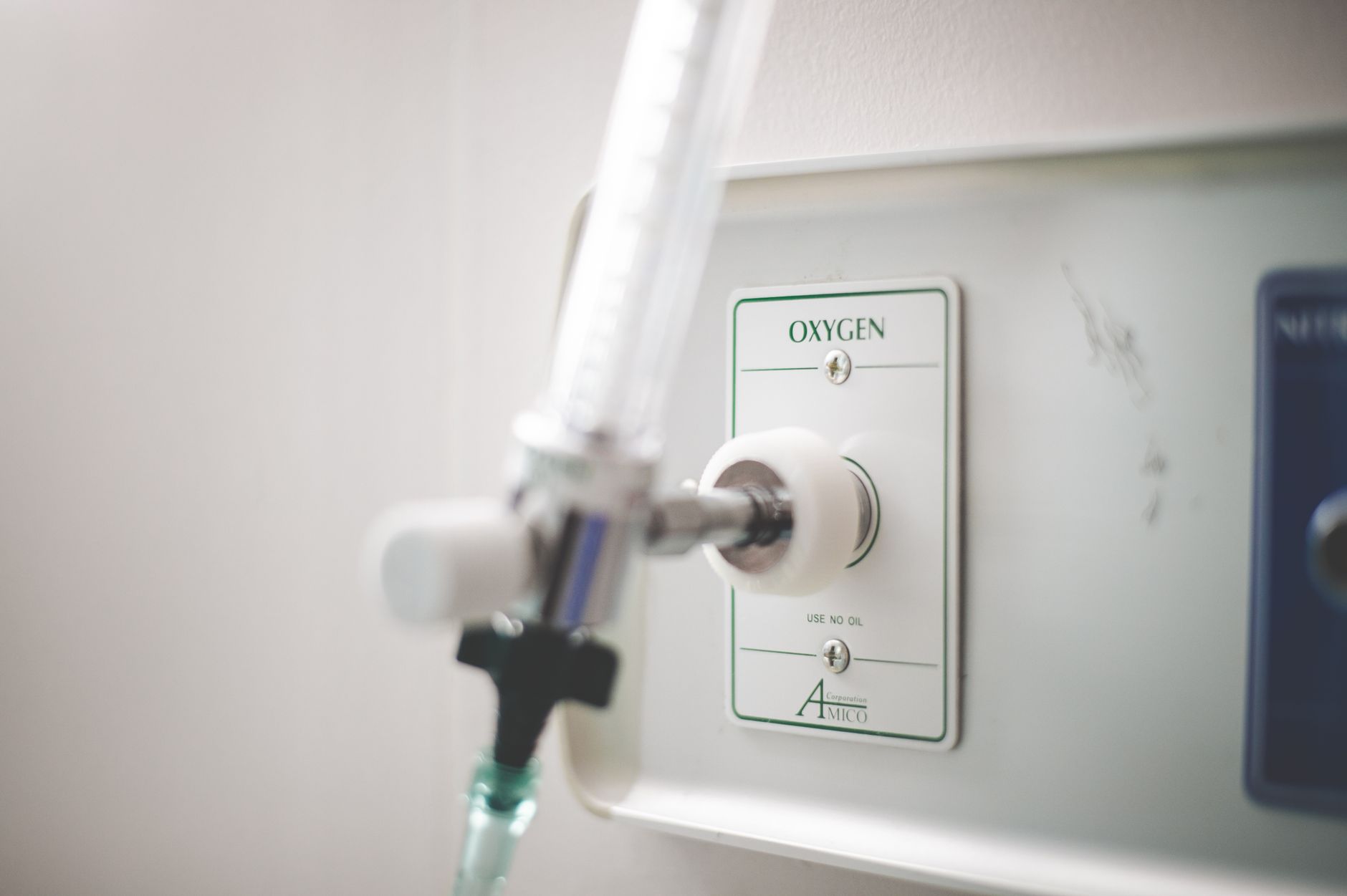 Medical & Dental Equipment →
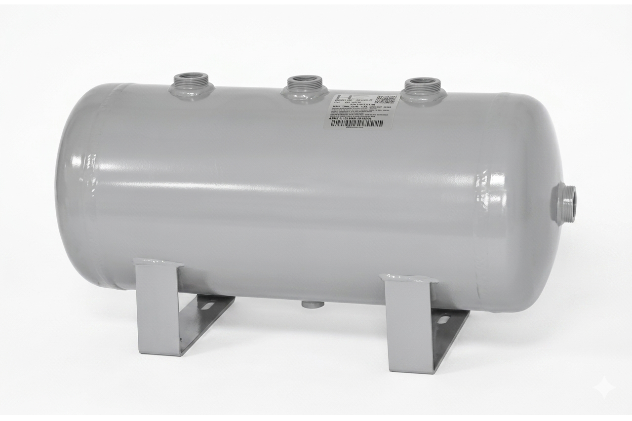
 Also applies to Compressor discharge monitoring · The single most universal install point for a pressure sensor · System header and demand-side monitoring · Filter differential monitoring (coalescing, particulate, activated carbon) · Dryer differential and outlet monitoring · Compressor sequencer and multi-machine load-sharing systems · Sensor count grows with machine count · Receiver tank and storage volume monitoring · Vacuum-side applications
Every entry is a real product on this site — linked, not just named. Quote them on the same line item.
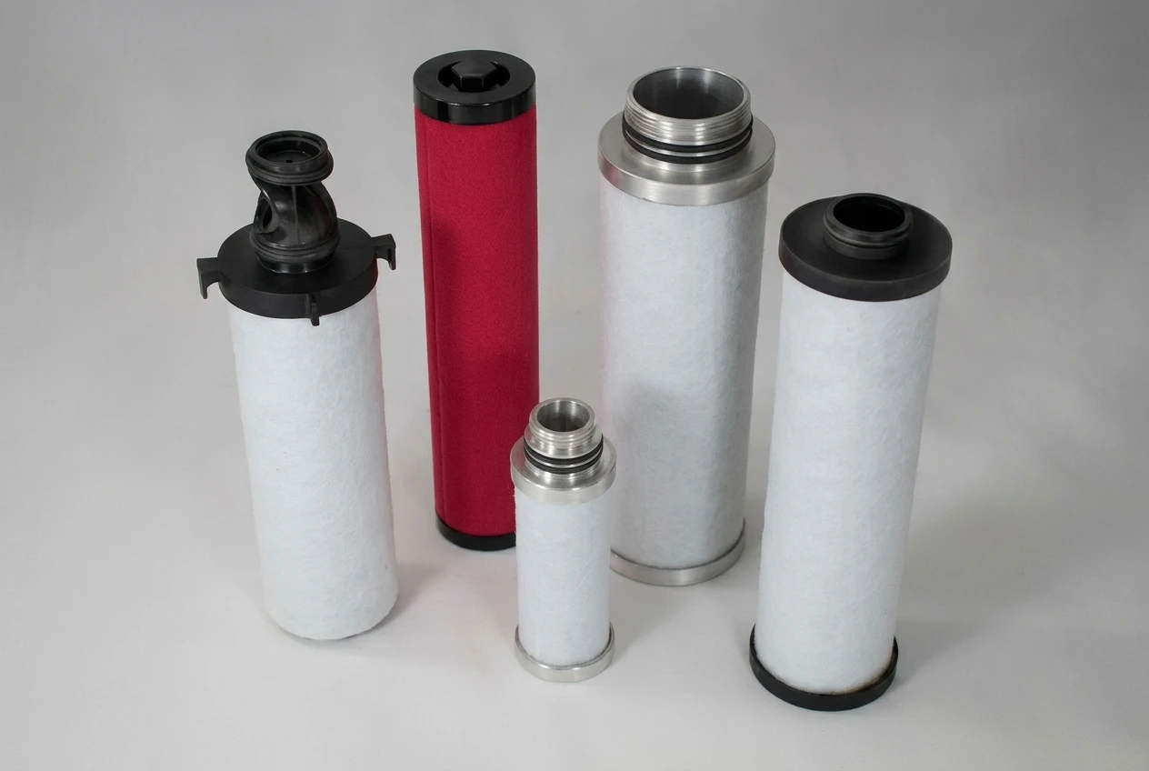
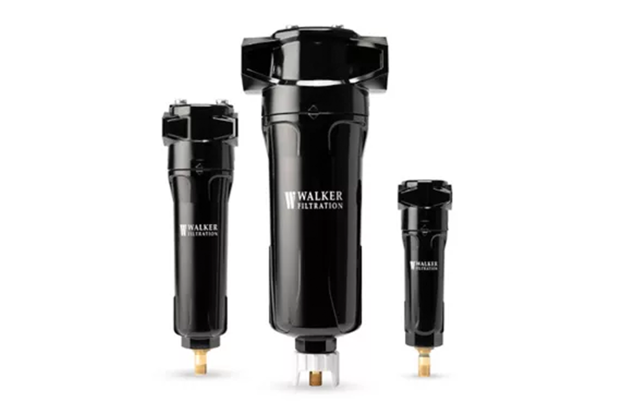

Filter-differential programs (sensors at every coalescing, particulate, and activated-carbon stage in the train) ship best as a coordinated kit — same sensor series, same port spec, same wiring convention. Multi-filter plants land at 6-12 sensors per skid.
Send us the application — a specialist routes you to the correct tier with a configured part. Lead-times and pricing returned within one business day.
—. We reply within one business day with pricing, lead-time, and configured parts.