DISTRIBUTOR-FIRST SUPPLY PARTNER · SINCE 1999 Live · Compressed Air System
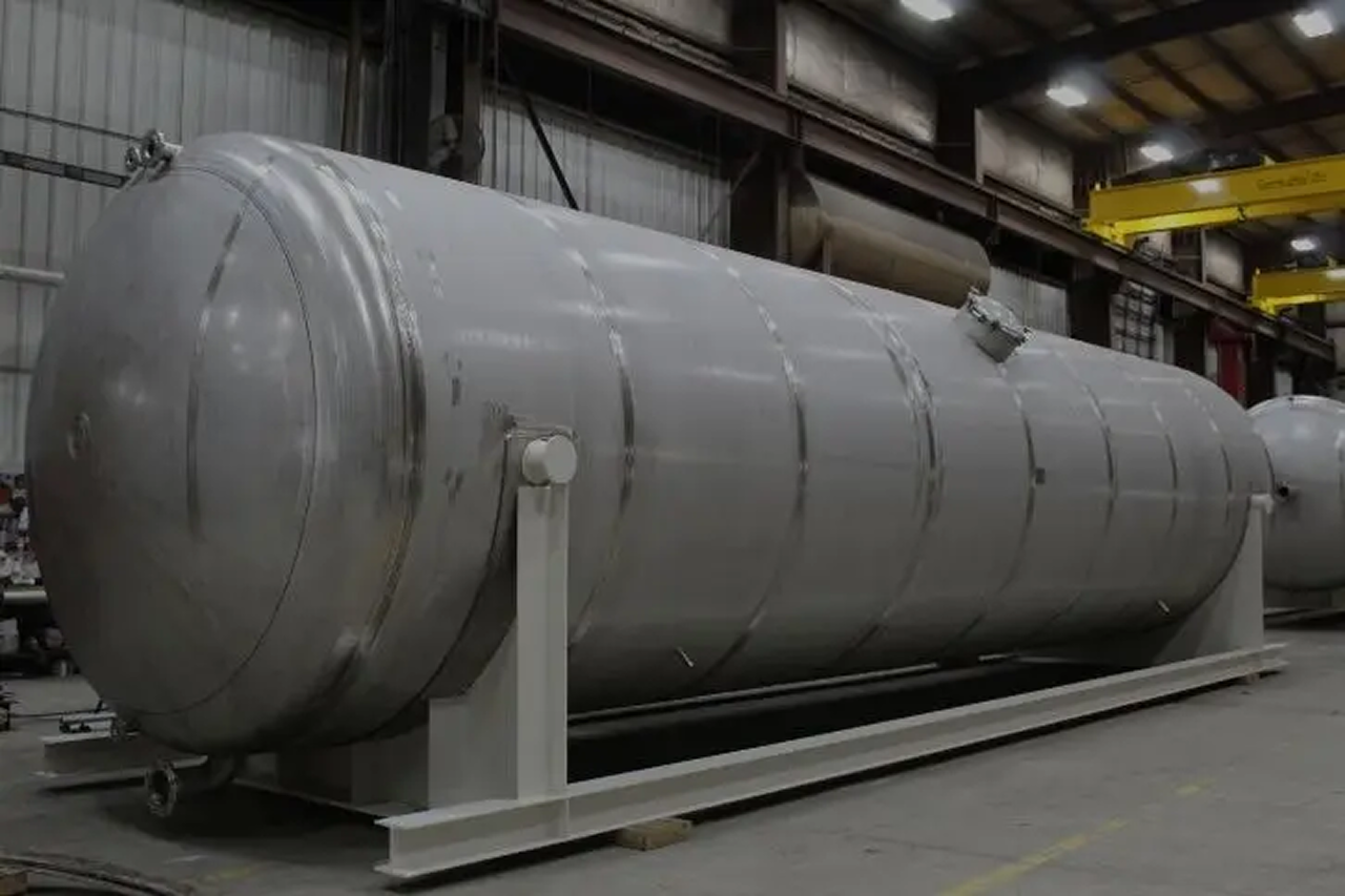
A vertical air receiver is the default storage vessel for a compressed air system — a steel ASME (American Society of Mechanical Engineers) Section VIII Division 1 pressure vessel mounted upright on four legs, installed between the compressor and the distribution piping. Vertical orientation occupies the smallest floor footprint for a given volume, which is why it is the standard choice in most compressor rooms. The same tank serves as a wet tank (set after the compressor and aftercooler, before the dryer) or a dry tank (set after the dryer, before distribution) — placement, not the vessel itself, defines the role.
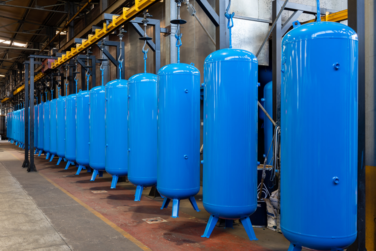
Why a vertical is the default storage call — and when it isn't. Scroll the strip →
A 1,060-gallon vertical takes 30-36 inches of floor diameter; the same gallons laid horizontal needs 20+ feet of length. The default storage choice in any compressor room with normal ceiling height.
Buffers demand surges so the compressor sees a slower-changing average. Short-cycling burns out air-end bearings, motor starters, and unloader valves in a fraction of their rated life — the receiver is the cheapest insurance against it.
Vertical column drops 60-80% of bulk water and oil out at one bottom drain on wet-tank service — maximum condensate residence time before the dryer sees it. Cleanest drain geometry of any tank format.
4-6 gal/CFM for fixed-speed compressors, 1-2 gal/CFM for VFD. Round up between catalog sizes — upsizing costs 15-20% on the tank and protects the air-end for its full service life.
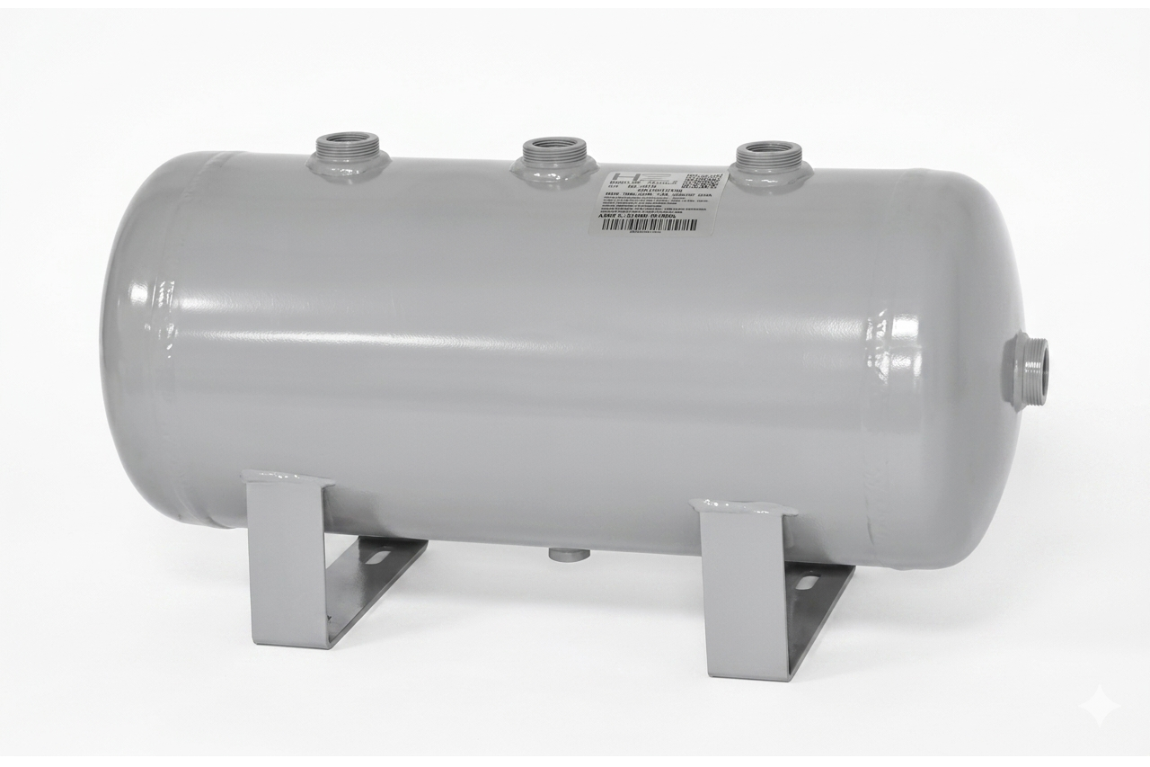
A 1,060-gallon vertical stands 9-11 feet tall plus 8-12 inches of relief-valve riser above the crown. Under 8 feet of clearance to steel rules out most verticals above 240 gallons. → Re-spec to horizontal-receiver-tank.
Packaged compressors above 40 HP often ship with the receiver lying under or behind the compressor on a shared skid. Vertical doesn't match the layout. → Re-spec to horizontal-receiver-tank coordinated with the OEM drawing.
Above 1,550 gallons, above 200 PSI MAWP, non-standard geometry, or multi-chamber service — the catalog stops. → Re-spec to specialty-custom-pressure-vessel with engineered fabrication and full U-1A documentation.
From the machine spec sheet → to the part number. Answer what you know — leave the rest blank — and send.
Most distributors sell one brand per product type. SPC's 60-brand portfolio means every Product Type page surfaces three real options matched to how your customer is buying today. Pick the tier; the quote desk handles the cross-reference.
Vertical is the default — quote vertical first, every time. If the ceiling won't fit or the customer is buying a skid-mount package, switch to horizontal. Don't let the customer guess at sizing — do the gal-per-CFM math and quote up if they're between sizes.
Each industry below uses this product across the listed areas. Open an industry to see how it fits the rest of its system.
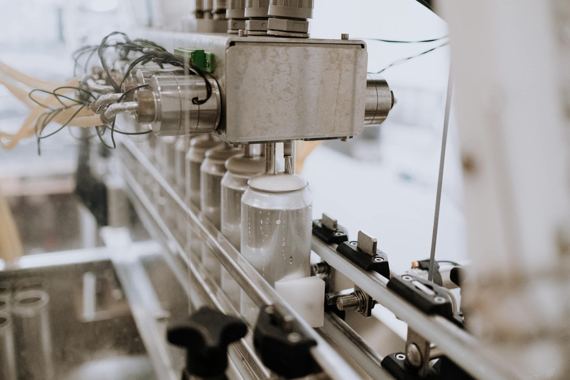 Food & Beverage Processing →
  Pharmaceutical, Medical Device & Laboratory →
 Also applies to Standard industrial compressor rooms (the default install) · Wet-tank service (between compressor and dryer) · 60-80% of total system condensate · Dry-tank service (downstream of the dryer) · Reciprocating compressor pulsation dampening · Standard practice on any piston install above 5 HP. · Duplex and triplex compressor systems · Compressor upgrades and capacity expansions · Standby and emergency air storage
Every entry is a real product on this site — linked, not just named. Quote them on the same line item.
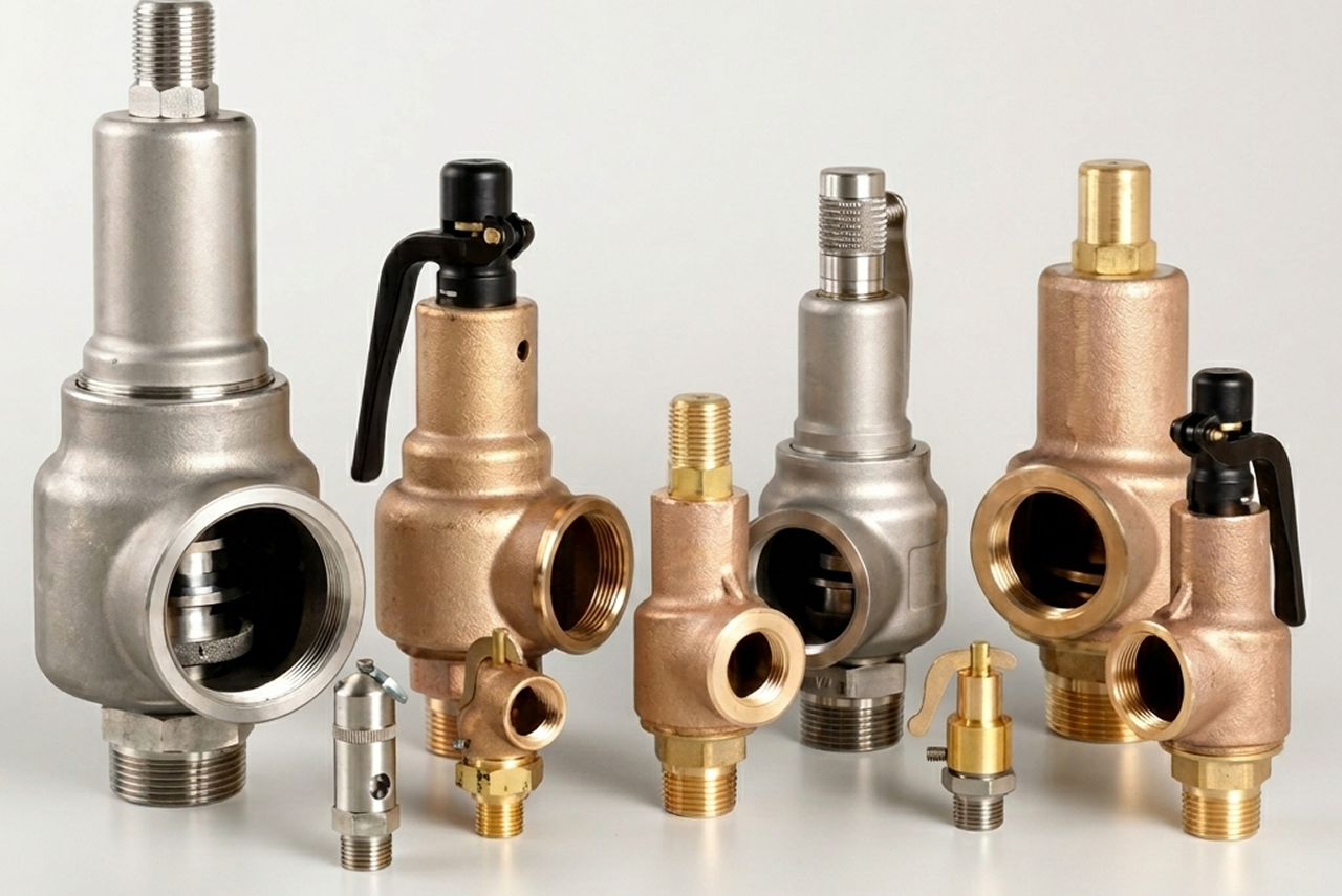
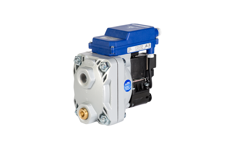

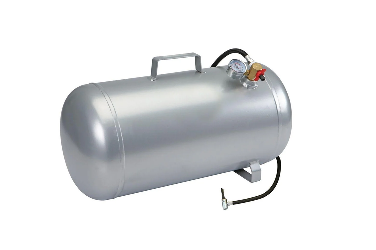
On compressor-room overhauls, quote the bundled kit — tank + fresh ASME safety relief valve + zero-air-loss drain + inlet/outlet pressure gauges + oil-water separator (wet service) — as one line. Bundling locks in the code-compliant install and prevents the customer from skipping accessories that fail state inspection.
Send us the application — a specialist routes you to the correct tier with a configured part. Lead-times and pricing returned within one business day.
—. We reply within one business day with pricing, lead-time, and configured parts.