DISTRIBUTOR-FIRST SUPPLY PARTNER · SINCE 1999 Live · Pneumatic Automation System
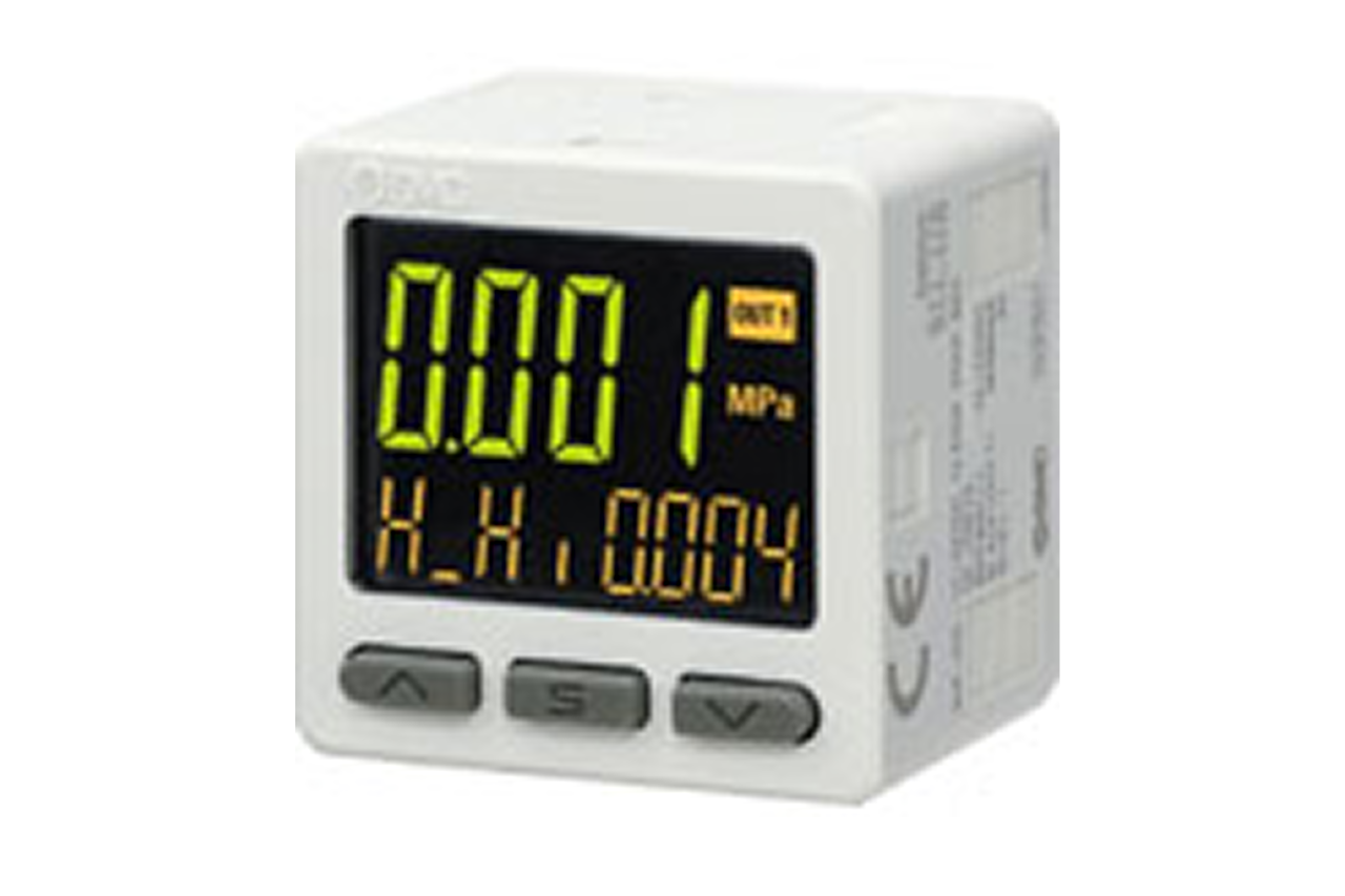
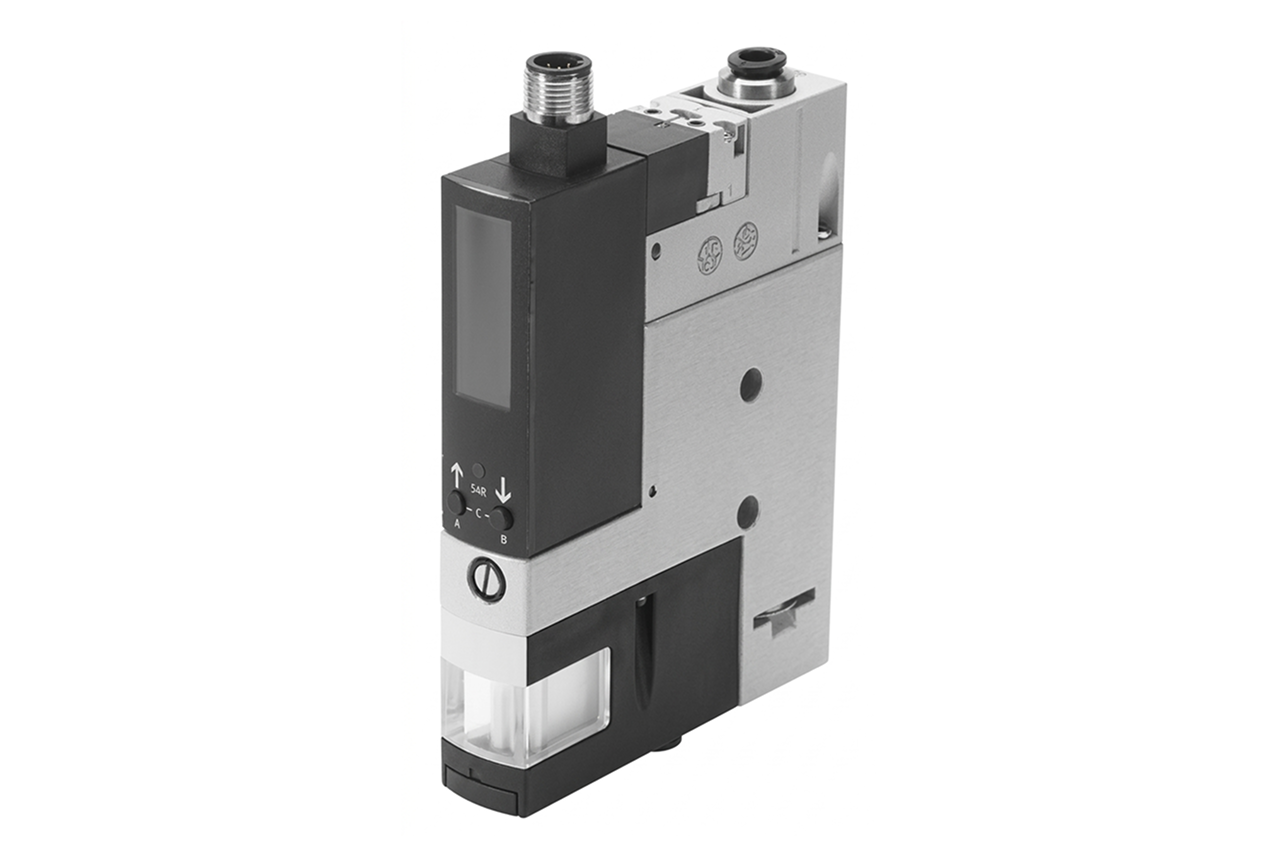
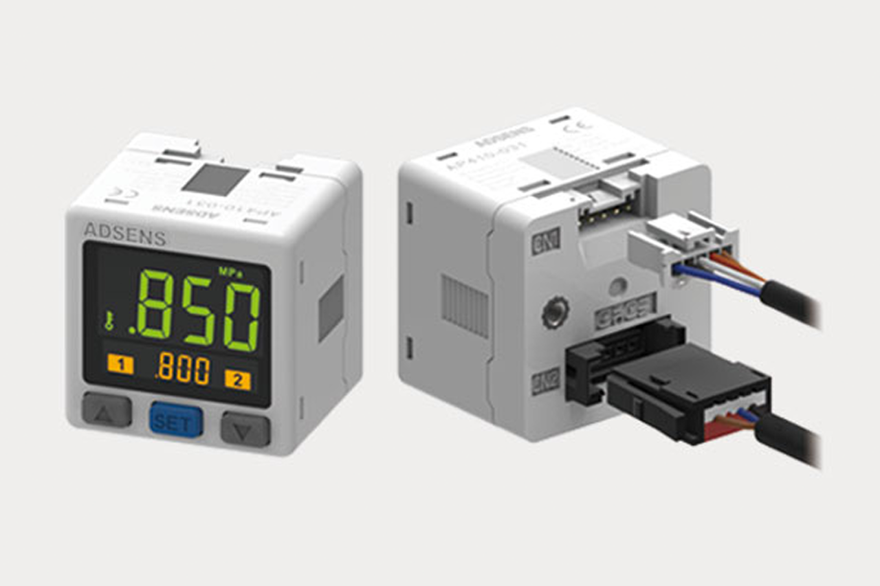
A vacuum sensor / switch is the verification device on a pick-and-place vacuum circuit — it monitors the live vacuum level and tells the PLC (programmable logic controller — the machine's control computer) whether the workpiece is actually gripped before the robot moves. It is one quarter of the vacuum end-effector sub-system: ejector + suction cup + vacuum sensor + replacement cup, sold and quoted together. The switch carries two adjustable set points — grip-confirm (releases the machine to move) and drop-detect (alarms a part lost mid-cycle) — and mounts on the EOAT (end-of-arm tooling) plate or in a tee within 6 inches of the cup. Without a switch, a machine can complete its motion with no part on the cup and collide with downstream equipment.
Tips and pointers on when to add vacuum verification — and where a switch alone won't save you. Scroll the strip →
A vacuum sensor / switch tells the PLC whether the part actually latched before the robot moves. Without it the machine operates on faith — and a lift with no part on the cup ends in a downstream collision.
Grip-confirm sits 10–15% below steady-state vacuum and releases the move command. Drop-detect sits 30–40% below and alarms a part lost mid-cycle. One device, two independent outputs into the PLC interlock.
Switching response is a few milliseconds — fast enough to catch seal loss within one PLC scan cycle. Operating range typically –20 to –27 inHg (inHg = inches of mercury); set points must be re-verified whenever the workpiece changes.
NPN vs. PNP output polarity must match the PLC input card — the most common install-day mismatch. Digital display for field tuning, basic switched for cost, IO-Link for continuous 16-bit vacuum value to the network. Compound range when the circuit alternates vacuum with positive blow-off.
The most common configuration failure on retrofits: switch reads vacuum correctly, output never lands in the move-permission rung. The hardware is useless without the PLC logic. → Wire grip-confirm into move-permission and drop-detect into alarm/abort at every install.
A switch tapped at the ejector or manifold reads reach vacuum, not cup vacuum — false grip-confirm before the cup actually seals. → Mount within 6 inches of the cup on the EOAT block or in a tee on the cup line.
A vacuum-only switch faults on positive pressure — and integrated blow-off blocks, test stands, and leak detectors cycle both. → Switch to compound-range variant for vacuum + positive pressure on the same line.
From the machine spec sheet → to the part number. Answer what you know — leave the rest blank — and send.
Most distributors sell one brand per product type. SPC's 60-brand portfolio means every Product Type page surfaces three real options matched to how your customer is buying today. Pick the tier; the quote desk handles the cross-reference.
The switch is the verification layer on every vacuum pick that matters. If the cost of a dropped part — broken tooling, scrap, recovery time — exceeds the switch cost by 5x or more, the switch is mandatory. That covers essentially every production pick.
Each industry below uses this product across the listed areas. Open an industry to see how it fits the rest of its system.
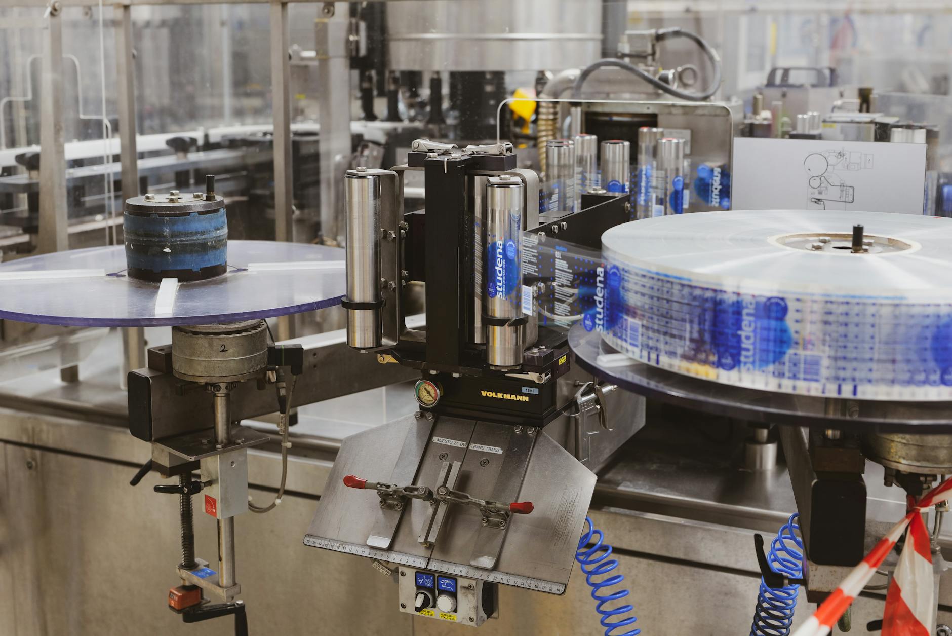 Packaging & Printing →
  Electronics & Semiconductor →
  Metalworking & Fabrication →
 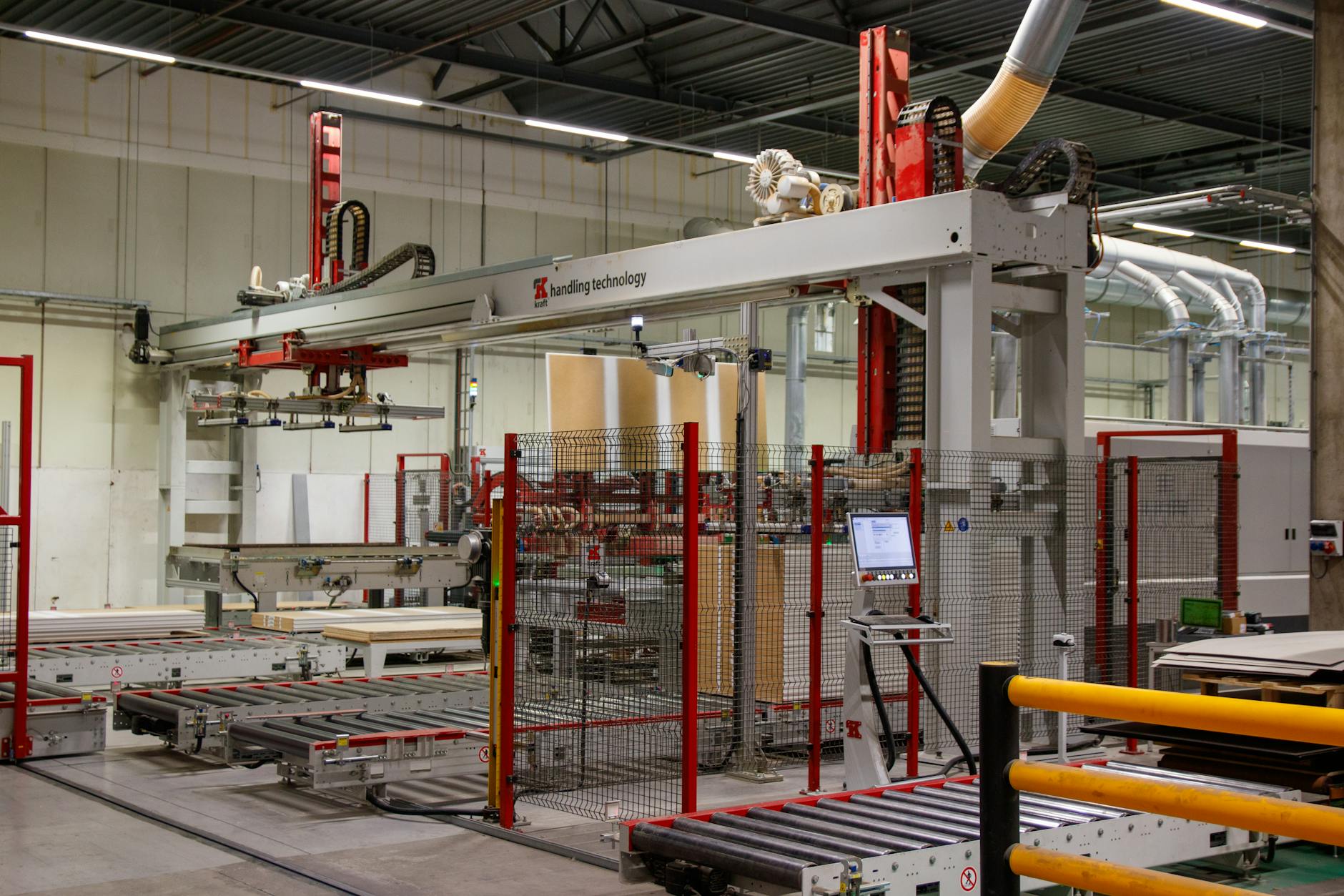 Material Handling & Conveyors →
 Also applies to Robotic EOAT on production pick-and-place · Test fixtures and inspection stands · Sheet-metal pick-and-place · Especially important on multi-sheet stack picking where double-blanking is a press-safety event. · Compound applications (vacuum + positive pressure on the same circuit)
Every entry is a real product on this site — linked, not just named. Quote them on the same line item.
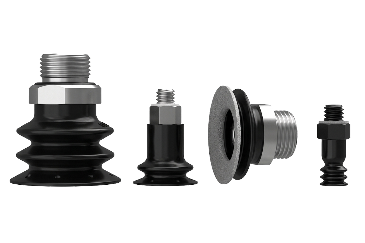
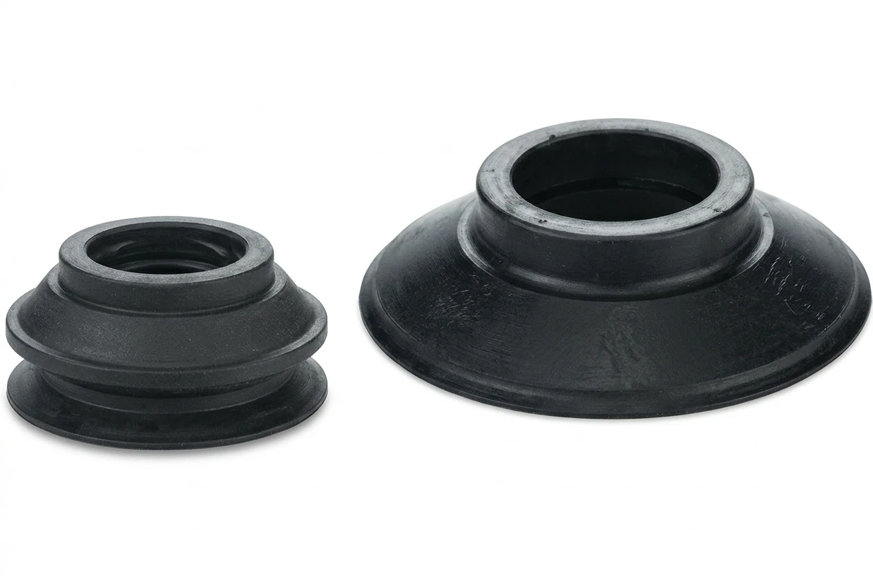
Switches are not bulk-consumed — solid-state transducers run for years. Stock one spare per installed switch in the MRO crib with pre-documented set points; a spare with the locked configuration turns a multi-hour outage into a 15-minute swap. The bulk-stock line that rides alongside switches is the matching replacement-vacuum-cup SKU.
Send us the application — a specialist routes you to the correct tier with a configured part. Lead-times and pricing returned within one business day.
—. We reply within one business day with pricing, lead-time, and configured parts.