DISTRIBUTOR-FIRST SUPPLY PARTNER · SINCE 1999 Live · Pneumatic Automation System
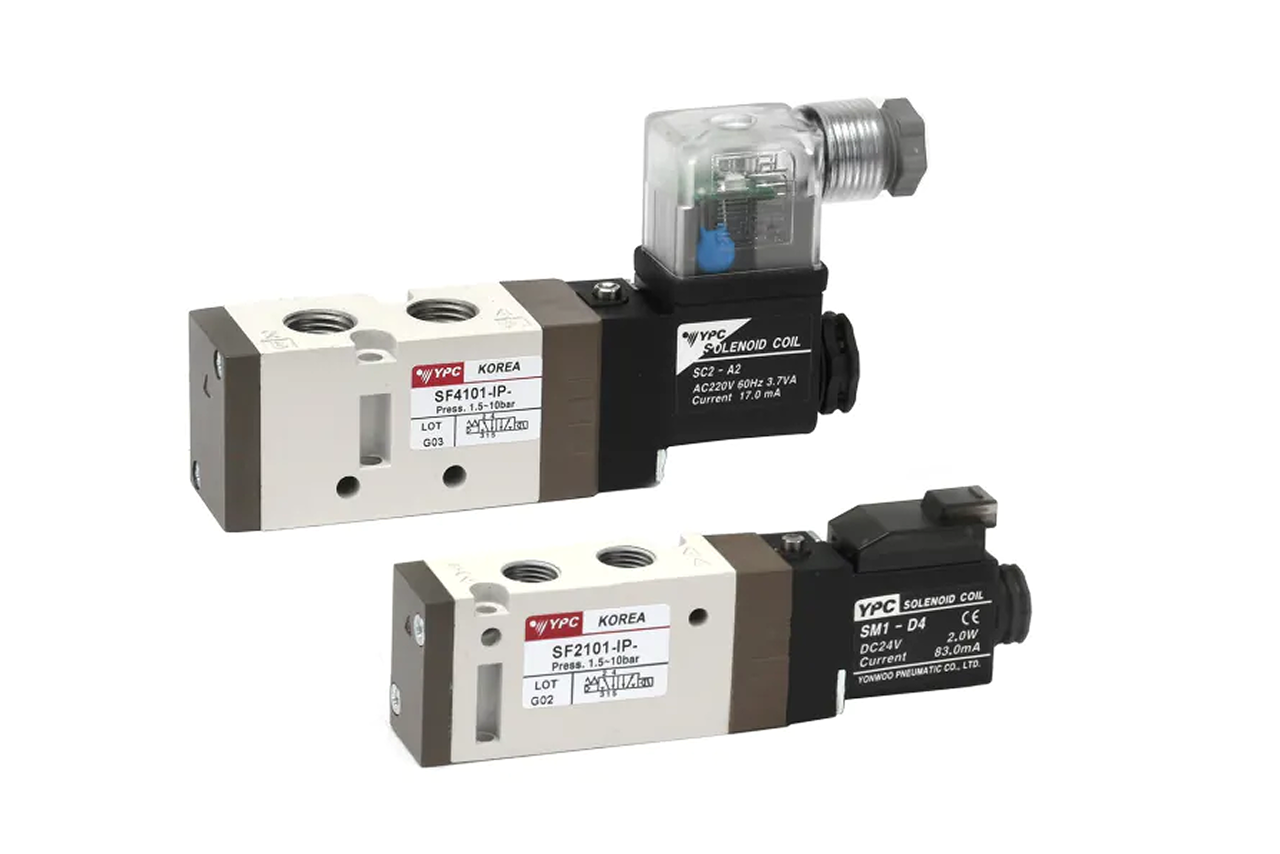
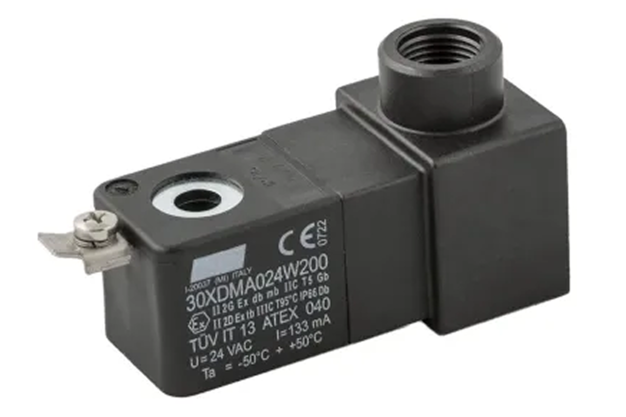
A solenoid valve is a directional control valve (DCV) shifted by an electric coil instead of a hand or foot. Energize the coil from a PLC (Programmable Logic Controller — the machine's electronic brain), push button, or sensor and the valve routes compressed air to a cylinder's ports; de-energize it and the valve returns or holds its last command. It is the universal bridge between the electrical control system and every pneumatic actuator on the machine — the single highest-unit-count active pneumatic component on any modern automated line, mounted inline at a single station or bolted to a shared sub-base manifold across 8 to 24 valves on one machine.
Tips and pointers on when the solenoid is the right DCV — and when to spec something else. Scroll the strip →
A 1.5–5 W coil at 24 VDC drives a tiny pilot; the pilot uses the inlet air to shift the main spool. Thirty solenoids run off PLC outputs with no power amplifiers — the universal electrical-to-pneumatic bridge.
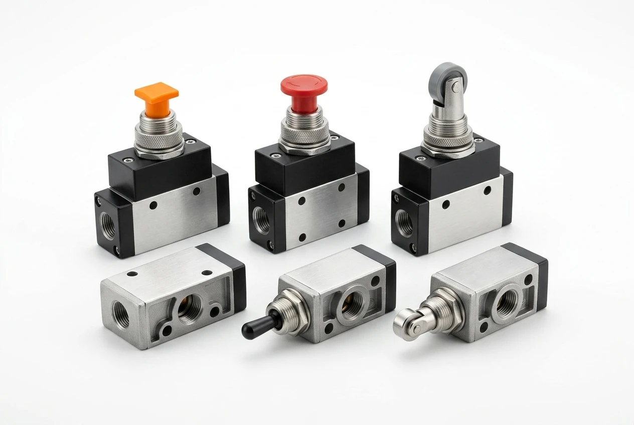
5/2 single springs to safe on power loss. 5/2 double holds last position (memory). 5/3 centers closed/open/pressure for hold or hand-move. 3/2 for single-acting or vacuum. One base series, four cylinder behaviors.
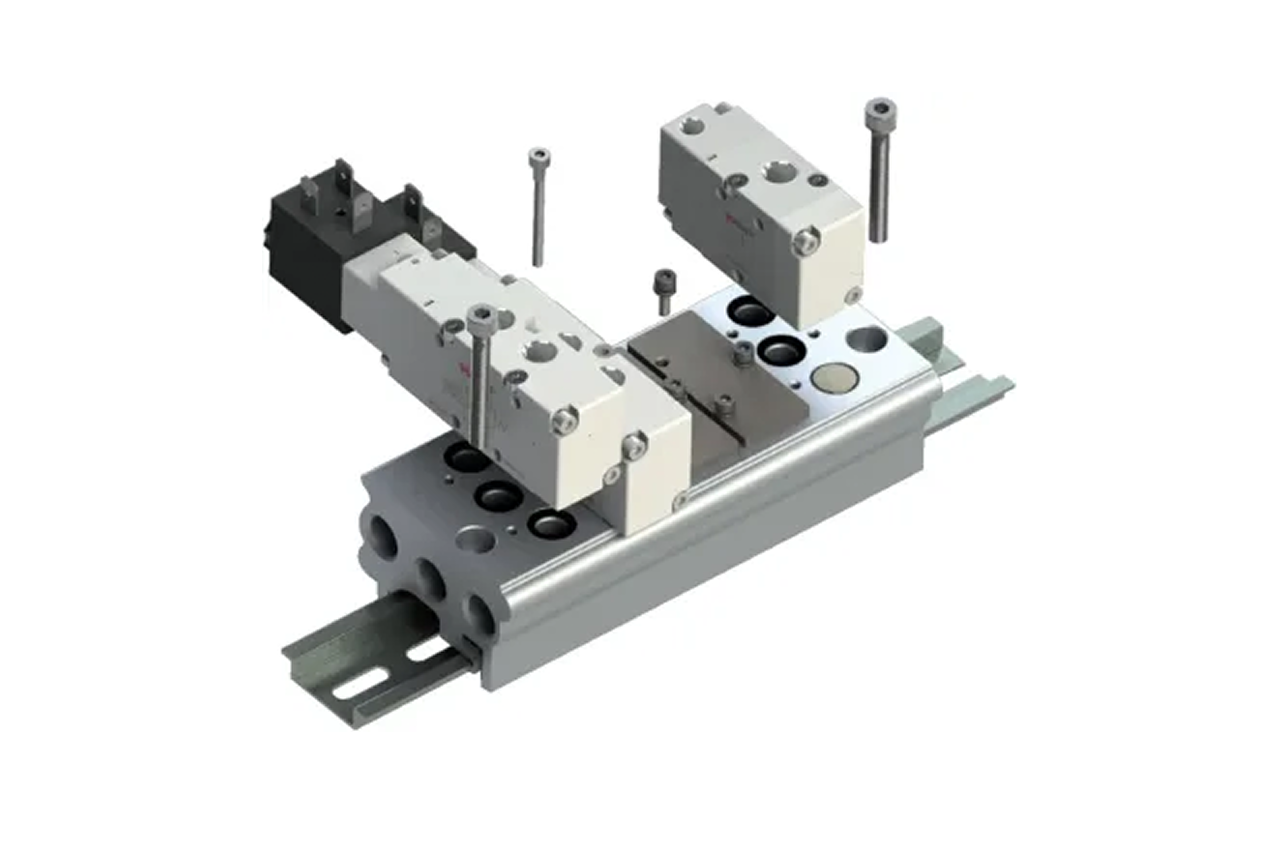
Industry Leader tier valves drop onto ISO 5599 / 15407 sub-bases — cross-brand swap on the same manifold, 50M+ cycle life on the Industry Leader tier for 24/7 packaging duty.
24 VDC is the modern default. 110/120 VAC is legacy US; 220/240 VAC is legacy European; 12 VDC is mobile. A 24 VDC coil on 110 VAC burns in seconds — confirm the PLC output spec before quoting, every time.
Coil arcs on switching; surface heats on duty. Either ignites a flammable gas or dust. → Re-spec to ATEX solenoid any time the location carries a Class/Division or ATEX zone classification.
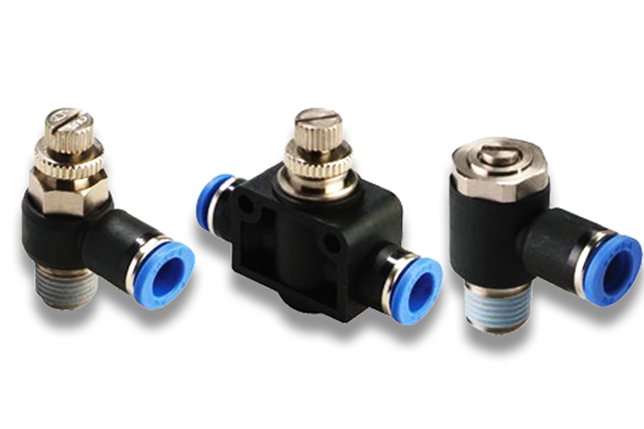
Pilot-operated valves silently won't shift below their pilot minimum — customer reports "cylinder not moving" with no other symptom. → Switch to a direct-acting variant for low-pressure or vacuum service (operates to 0 PSI, lower flow).
Loose inline valves stop scaling at the 8th station — fittings, wiring, and cabinet space dominate the build. → Switch to manifold sub-base, or step up to IO-Link valve terminal if the customer has an IIoT initiative or wants per-valve diagnostics.
From the machine spec sheet → to the part number. Answer what you know — leave the rest blank — and send.
Most distributors sell one brand per product type. SPC's 60-brand portfolio means every Product Type page surfaces three real options matched to how your customer is buying today. Pick the tier; the quote desk handles the cross-reference.
The cylinder is the line item the customer asks for. The solenoid valve is the line item that stays on the quote every time and turns one cylinder sale into a full circuit sale.
Each industry below uses this product across the listed areas. Open an industry to see how it fits the rest of its system.
 Pharmaceutical, Medical Device & Laboratory →
 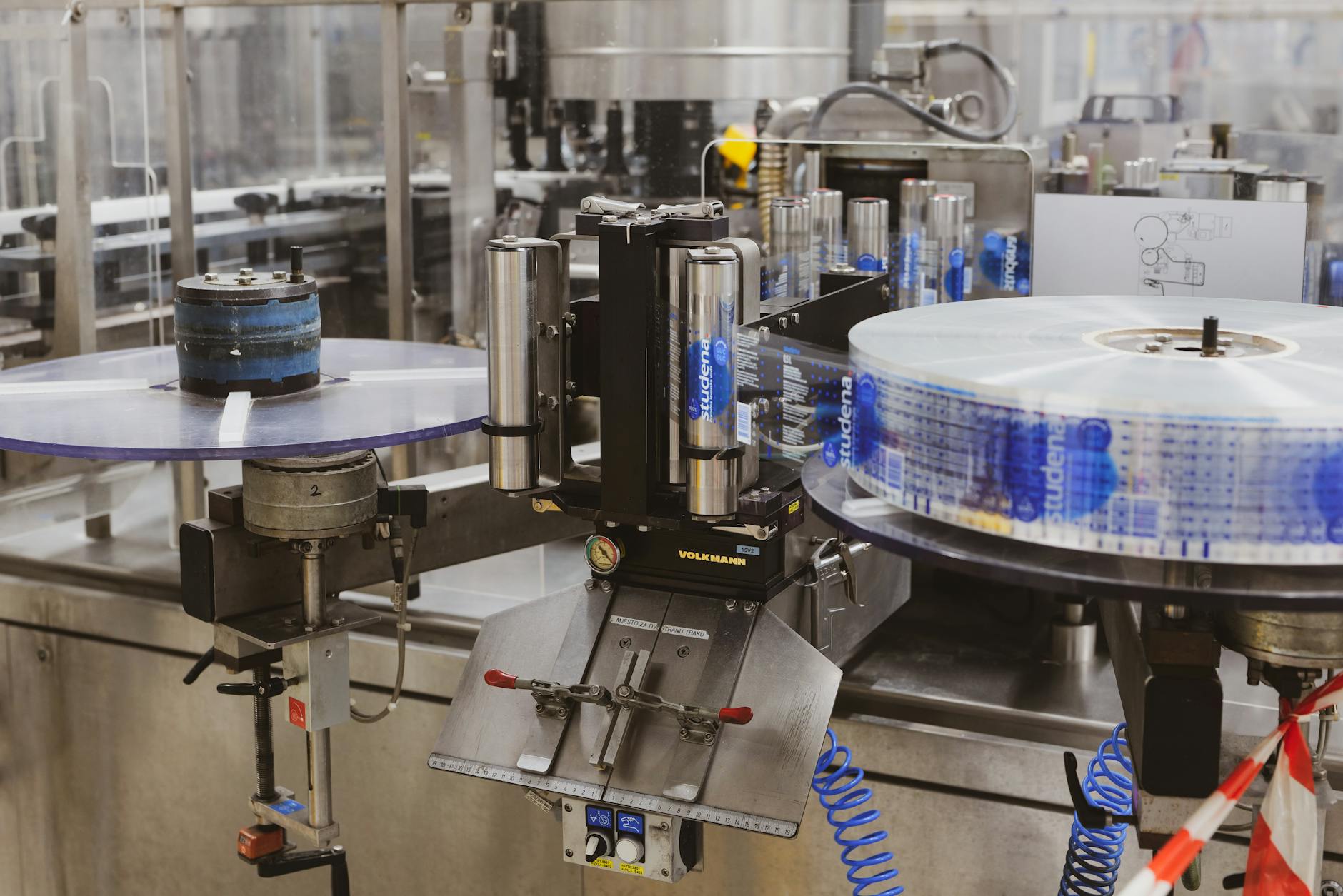 Packaging & Printing →
 Also applies to OEM automation — the universal directional control element. · Retrofit and machine modernization. · Single-station manual work cells. · Mobile and off-highway equipment. · Vacuum and air-motor control.
Every entry is a real product on this site — linked, not just named. Quote them on the same line item.
Stock the plant's standard-coil-voltage spare on the maintenance shelf. A wrong-voltage coil at a Saturday-morning service call is worse than no coil — burns instantly when wired. One 24 VDC coil + one seal kit per high-cycle station is the minimum spare-parts position.
Send us the application — a specialist routes you to the correct tier with a configured part. Lead-times and pricing returned within one business day.
—. We reply within one business day with pricing, lead-time, and configured parts.