DISTRIBUTOR-FIRST SUPPLY PARTNER · SINCE 1999 Live · Compressed Air System
SPC Company
Compressed Air / Monitoring / Air Quality / Air Quality Analyzer — ISO 8573-1
Layer 07 · Monitoring Emerging · CS Instruments
01What it is

Air Quality Analyzer — ISO 8573-1

The instrument set that documents compressed air purity against ISO 8573-1 — the international standard that rates compressed air by three contaminants (solid particles, water, and oil) and reports the result as a three-digit class code, one digit per contaminant, with a lower number meaning cleaner air. Full measurement is not one instrument but three sensors plus a consolidating data logger — a laser particle counter, a dew point sensor, and a residual oil sensor — installed downstream of the entire treatment train at the point where air contacts product. It sits in the monitoring layer as the documentation tool: it does not condition the air, it produces the audit-grade record an FDA, USDA, GFSI, or notified-body inspector will ask for.

Real-world reference Representative air quality analyzer — iso 8573-1
Air Quality Analyzer — ISO 8573-1 — representative product photo
02Why it's needed

Why this matters.

Tips and pointers on when the full ISO 8573-1 analyzer set is the right call — and when to spec something else. Scroll the strip →

01 · Key point
It produces the audit record.

ISO 8573-1 class code (e.g. 1.2.1) documented on a continuous logged trail. An inspector arrives, the plant produces the record on demand — that is the difference between conformance and a finding.

02 · Key point
Three sensors, one record.

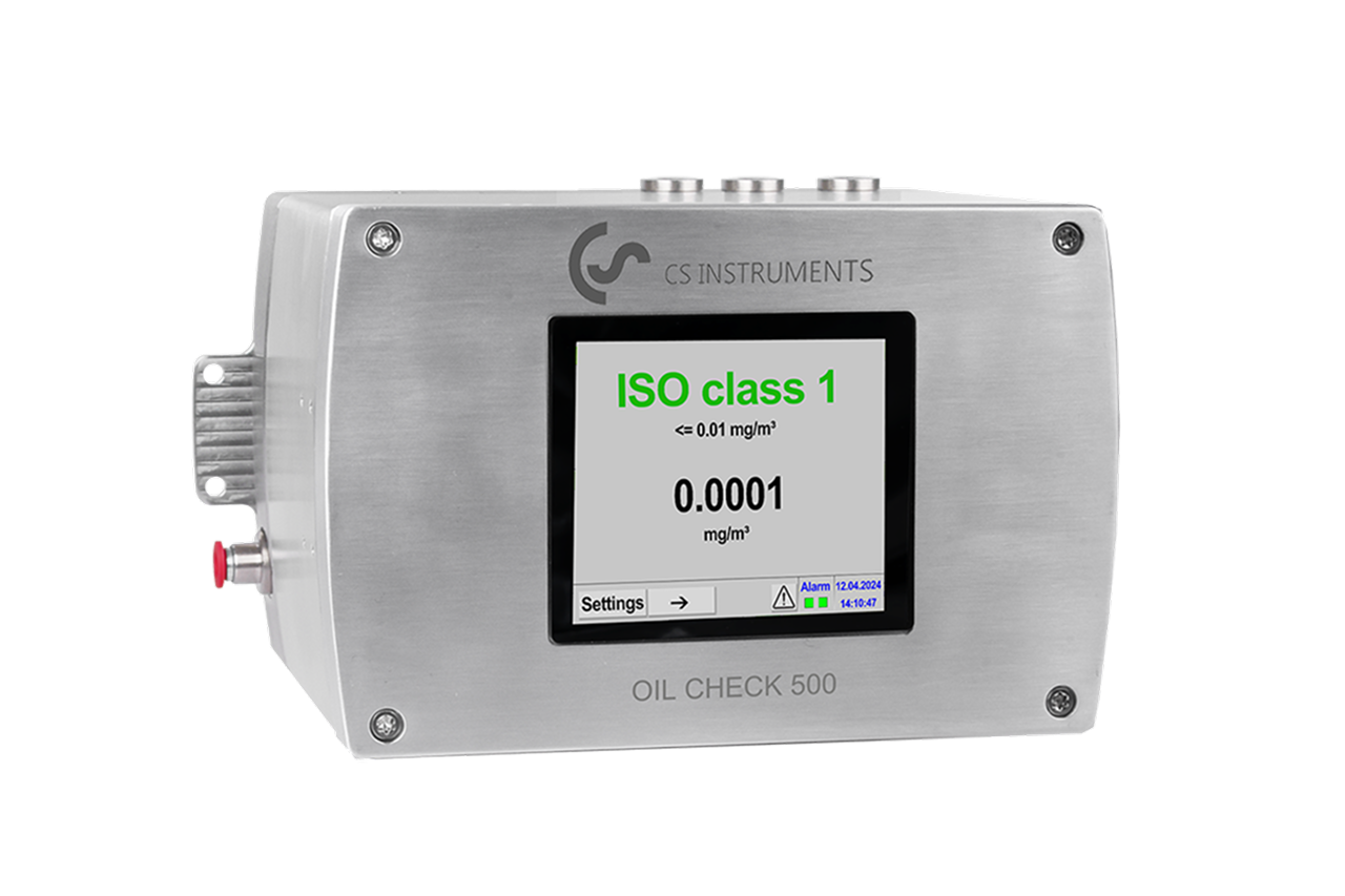
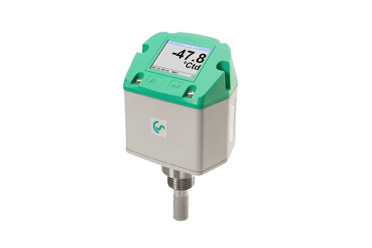
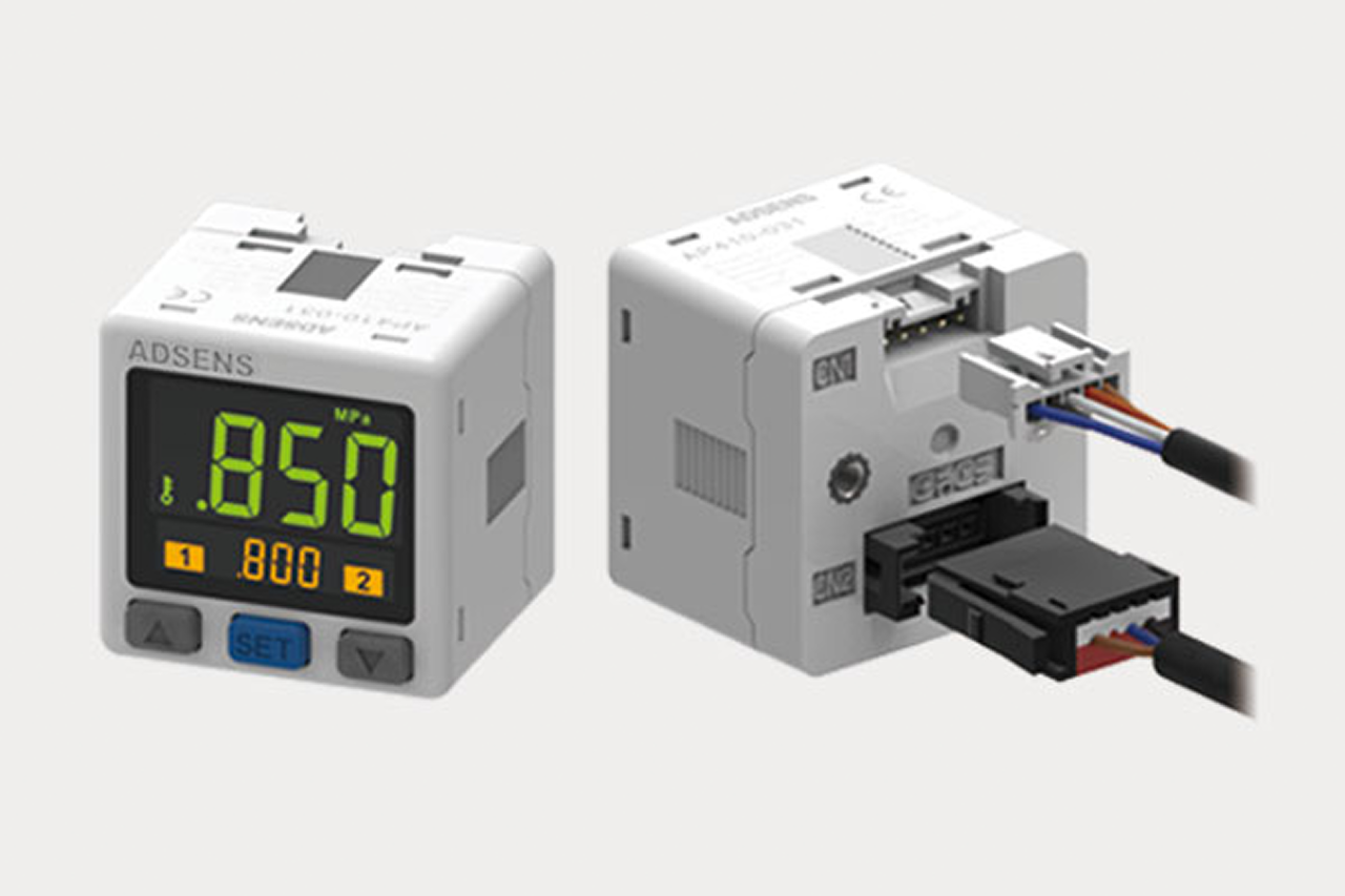
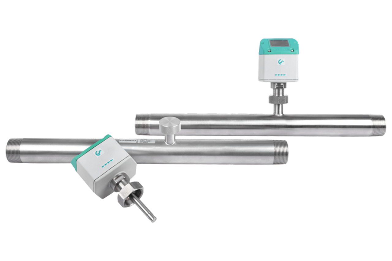
Laser particle counter to 0.1 µm, polymer-capacitive PDP sensor, PID-based oil sensor in the low mg/m³ range — consolidated by a logger over Modbus into one time-stamped audit trail with months of history.

03 · Key point
It proves Class 0 claims.

"We run an oil-free compressor" is not documentation. ISO 8573-1 Class 0 still requires measurement — the analyzer's oil reading is the proof that closes the audit finding.

04 · Pro tip
Scope to actual compliance.

Scope sensors to the customer's audit, not the three-parameter default. Water-only audit → dew point monitor. Food contact with documented oil-free → particles + water. Pharma fill line → full three-parameter set.

05 · Where not to use
Install at dryer outlet for point-of-use cert.

ISO 8573-1 is verified where air contacts product, not at the dryer. → Re-locate sample tap downstream of final point-of-use filtration; a dryer-outlet reading does not certify the air the product touches.

06 · Where not to use
Import-tier sensors for audited installs.

Auditors ask for calibration certificates and sensing-method validation — import-tier kit can't produce them. → Spec audit-grade sensors with documented calibration program; old uncalibrated sensors are failed equipment for audit purposes.

07 · Where not to use
Without a written SOP.

An instrument without documented readback procedure, calibration cadence, and alarm response is half a deliverable. → Hand off a written SOP with the install — the paperwork is what closes the auditor finding, not the sensor on the wall.

03Key selection criteria

What we need to spec it right.

From the machine spec sheet → to the part number. Answer what you know — leave the rest blank — and send.

01 · Input
Pull from the audit requirement — class code (e.g. 1.2.1) sets both which of the three contaminants need instrumentation and the measurement resolution. Scope to actual compliance, not the three-parameter default.
Water only (e.g. x.2.x — dew point monitor) · Particles + water (food contact, documented oil-free) · Full three-parameter (particles + water + oil — pharma, USP <797>/<800>, NFPA 99)
02 · Input
Sets calibration cadence, documentation depth, and alarm-response SOP requirements. Each driver carries its own audit norms.
FDA 21 CFR Part 211 (pharma) · GFSI / SQF / BRC (food) · USP <797> / <800> (compounding) · NFPA 99 (medical breathing air) · ISO 14644 (cleanroom)
03 · Input
Tap as close to the certified point of use as practical, downstream of any final point-of-use filtration. A dryer-outlet reading does not certify the air the product touches. Confirm process connection and line pressure.
G1/2 BSP · 1/2 NPT · Up to 16 bar / 232 PSI (standard) · 40 bar / 580 PSI (HP variant)
04 · Input
Continuous certification at a single point of use (fixed set + logger) or scheduled spot testing across multiple points/sites (portable kit)? Driver determines deployment shape and quote total.
Fixed install (continuous, single point) · Portable audit kit (multi-point, multi-site) · Hybrid (portable for baseline + fixed at priority points)
05 · Input
Feeds plant historian or standalone logger? Modbus-RTU carries calibration and diagnostic data alongside readings — preferred for audit-grade. Minimum two-year readback retention is typical.
Standalone logger (onboard SD / USB) · 4-20 mA analog (per sensor) · Modbus-RTU / RS-485 (audit-grade, historian-integrated)
06 · Input
Most installs need 1 sensor set (particles + water + oil + logger) per certified point of use. Multi-point pharma/food plants scope a separate set per critical point. Portable audit kits typically 1 per consultancy.
1 set (single point of use) · 2-4 sets (multi-point pharma / food) · 5+ sets (multi-line fill or multi-building)

Need different sizes, colors, or quantities? Fill the form, add to quote, then fill again — each click is one quote line.

04Choose your solution tier  ·  core differentiator

Whatever your lever — spec, value, or price — SPC has the right brand.

Most distributors sell one brand per product type. SPC's 60-brand portfolio means every Product Type page surfaces three real options matched to how your customer is buying today. Pick the tier; the quote desk handles the cross-reference.

05How to sell this  ·  distributor talk track

The tier conversation closes the deal. The cross-reference catalog wins the next one.

You can build the cleanest compressed air system in the country, but if the plant cannot produce a logged ISO 8573-1 record on demand, the auditor calls it unverified — and unverified air is non-conforming air.
The SPC difference · how distributors actually buy

The 30-second positioning

Analyzers sell on regulatory necessity. Every customer here has an external auditor who has either already asked for purity documentation or will at the next inspection. Scope the instrument set against the customer's actual compliance scope, not the full three-parameter default — many customers need only two of the three.
Tier: The SPC reference for ISO 8573-1 is an Industry Leader tier analyzer set with PID-based residual oil sensing, optical particle counting to the most stringent classes, integrated dew point, and Modbus standard. Economical / import-tier does not exist meaningfully here — auditors will ask for the calibration certificate and sensing-method validation, and import-tier kit cannot produce them.

Customer cue → talk move

""Our auditor flagged compressed air purity as a gap""
The lead customer. Get the auditing body (FDA 21 CFR Part 211, GFSI/SQF/BRC, USP <797>/<800>, ISO 14644, NFPA 99), get the target ISO 8573-1 class, scope the instrument set to exactly that. Tie the install to a written SOP (Standard Operating Procedure) — that is what closes the auditor finding.
""We just need to verify the dryer""
If only the water digit is in scope, this is a dew-point-monitor sale, not the full analyzer. Pivot down.
""We run oil-free compressors so oil is excluded""
True only if the oil-free designation is documented and downstream piping has no oil-bearing equipment. Class 0 still requires measurement to prove it. Reframe oil measurement as the proof of the Class 0 claim, not redundant verification.
""We want one box that does everything""
No such product exists at audit-grade. Three sensors plus a logger; build the conversation around the consolidated logger as the "one screen" the operator sees.
""How often does this need calibration?""
Annually per sensor; pharma audits often want every 6 months. Quote the calibration program at the same time as the instrument — calibration is not optional for audit work.
""Can we just do periodic third-party sampling instead?""
For some compliance scopes acceptable, but audit trail is thinner and contamination events between samples are missed. Fixed-install wins when the cost of a missed event exceeds the cost of the instrument — almost always true in pharma, frequently in food and electronics.
""Our existing instrumentation is 8 years old and not on a calibration program""
It is failed equipment for audit purposes. Old uncalibrated sensors produce numbers but not auditable numbers. Quote replacement + calibration program; the customer has been carrying exposure they didn't know about.
09Install · 6 critical steps

The things that matter on the first install.

Step 01
Confirm the install point matches the compliance scope
ISO 8573-1 is verified at the point where the air touches product, not at the dryer outlet. Walk the piping from the certified point of use back toward the dryer; the instrumentation tap should be as close to the point of use as practical, downstream of any final point-of-use filtration. A reading at the dryer outlet does not certify the point-of-use air if there are tens of feet of pipe between.
Step 02
Plumb a dedicated sample loop
Audit-grade installs use a small-diameter line drawing controlled sample flow from the main pipe to the instrument. The sample loop isolates the sensors from main-line transients, gives each sensor its rated flow, and lets sensors be removed for calibration without depressurizing the production line. Include a pressure regulator and flow-control orifice in the loop — pressure transients during compressor unload cycles otherwise produce false alarms.
Step 03
Install particle, dew-point, and oil sensors per the manufacturer's orientation spec
Particle counters install vertical-up flow to prevent particle settling in the sample cell. Dew-point sensors install per probe-direction marking. Oil sensors require a stabilization period (sometimes hours) after first power-up before they read accurately — stage the install so the customer is not expecting a final reading at the moment of energization.
Step 04
Wire each sensor to the data logger or plant historian
4-20 mA is the baseline; Modbus-RTU (RS-485 serial bus) is preferred for audit-grade installs because it carries diagnostic and calibration data alongside the reading. An instrument without a logged trail is not an audit instrument. Confirm the historian retention — most compliance regimes require minimum two-year readback.
Step 05
Configure alarm setpoints to ISO 8573-1 class boundaries
Set thresholds at the class boundary for each parameter (or one step inside for safety margin). Route alarms to the plant control system or operator HMI. Document the alarm setpoints in the SOP — auditors verify the setpoints match the customer's stated class.
Step 06
Hand off documentation to the customer's quality team
Deliver calibration certificates, install drawings, wiring diagram, alarm-setpoint config, and a written SOP covering routine readback, calibration schedule, and alarm response. The instrument is half the deliverable; the documentation package is the other half, and is what makes the install audit-ready. Schedule the next calibration date on the customer's service calendar.
10Troubleshoot · top failures

Most returns trace to one of these causes.

Symptom
Most likely cause
Fix
Oil sensor reads near zero on a known oil-bearing system.
Sensor warm-up incomplete (PID detection requires stabilization, sometimes hours after power-up), sample line contaminated with activated carbon or oil-adsorbent material scrubbing the oil signal, sample flow below rated range, or sensor UV lamp at end of life.
Confirm continuous power for the manufacturer-specified stabilization window. Inspect the sample line for unintended adsorbent material. Verify sample flow against the datasheet. If all correct and reading remains anomalous, schedule a calibration check — the sensor may need lamp replacement.
Particle count spikes intermittently with no apparent system event.
Sample cell contamination (particles deposited on optical surfaces), backflow into the sensor, ambient vibration coupling into the optical bench, or a transient pressure-drop event flashing condensed moisture as false particle counts.
Clean the sample cell per OEM procedure. Confirm the sample-line check valve is functioning. Move the install away from mechanical vibration sources (reciprocating compressor, vibrating screen). If spikes correlate with pressure fluctuations, install a pressure-stabilizing component upstream of the sample tap.
PDP reading drifts upward over weeks and doesn't return after a wet-air event.
Sensor element hit with bulk liquid water beyond recovery capability, sensor at end of calibration interval drifting, or upstream desiccant dryer is genuinely losing performance (the instrument is doing its job — the dryer is the problem).
First confirm the dryer — tower differential pressure, regeneration cycle, desiccant condition. If dryer verified healthy, pull the sensor for calibration verification or factory service. Maintain a calibrated spare sensor on the shelf for critical installs.
Modbus communication to the data logger drops intermittently.
RS-485 termination missing or incorrect (need 120Ω at both bus ends), excessive bus length, VFD (Variable Frequency Drive) harmonics coupling from nearby power runs, or polling rate too aggressive for the slowest sensor.
Verify proper RS-485 termination. Confirm cable shielding grounded at one end only. Move bus cabling away from VFD power runs or shield adequately. Reduce polling rate to match the slowest sensor. Persistent issues with multiple sensors point to a logger-side configuration issue.
Alarm fires repeatedly during compressor unload cycles.
Pressure transients during unload cycles passing through the sample loop, momentarily disturbing the sensors. Particle counters and oil sensors are particularly sensitive to flow disturbances; the alarm is real to the instrument but not a true class excursion.
Add a flow-stabilizing orifice or pressure regulator to the sample loop so the instruments see steady sample flow regardless of main-line transients. Configure the logger to suppress alarms shorter than a manufacturer-specified duration (typically several seconds).
Auditor questions the chain of custody on the recorded data.
Data logger time not synchronized to plant or audit-traceable time source; readings stored only locally without backup; or no procedure documenting how readings are retrieved and reviewed.
Synchronize the logger to a plant NTP (Network Time Protocol) source or audit-traceable time reference. Configure backup to a secondary system. Write or update the SOP to cover daily/weekly readback procedure with a named responsible role. This is a paperwork fix more than an instrument fix — often the audit gap that surfaces in the first inspection after install.

Get the right air quality analyzer — iso 8573-1 on quote in 24 hours.

Send us the application — a specialist routes you to the correct tier with a configured part. Lead-times and pricing returned within one business day.

Request a quote