DISTRIBUTOR-FIRST SUPPLY PARTNER · SINCE 1999 Live · Pneumatic Automation System
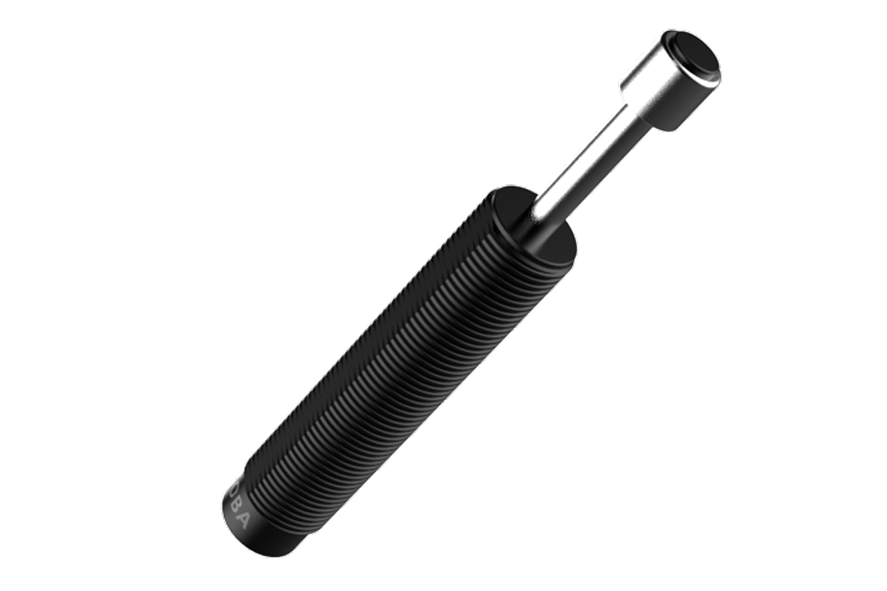
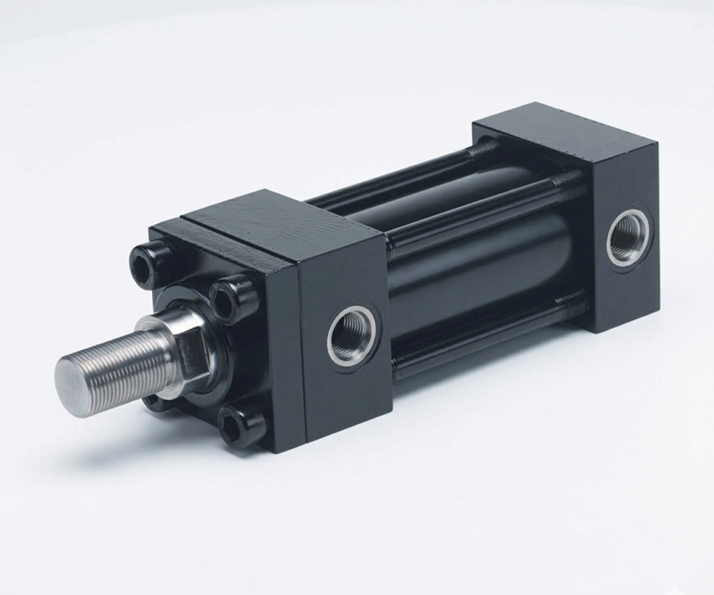
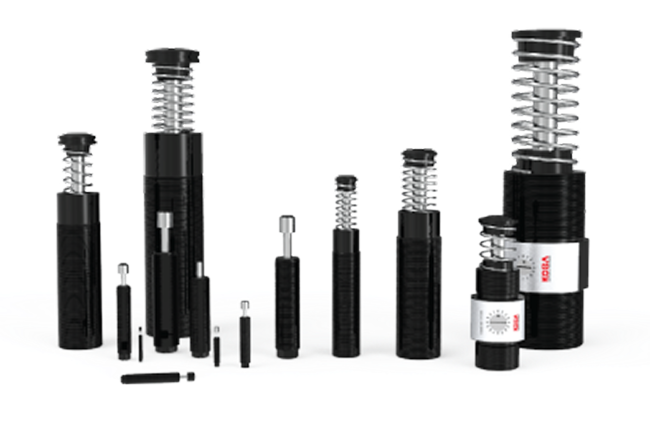
A self-compensating pneumatic shock absorber is a fixed-rating end-of-stroke decelerator that brings a moving pneumatic load smoothly to rest without any external adjustment. Internal metering — a profiled set of orifices engineered into the body — automatically adapts the damping force to the incoming energy across the unit's rated range, so one unit handles a span of load-and-velocity combinations as built. It threads into the machine frame on a standard mounting thread (M6, M8, M10, M14, M20, M27 covering most ranges) and is installed wherever a cylinder, gantry, or EOAT would otherwise hit a hard stop. The trade-off for that simplicity is fixed behavior: if the application's load or speed later changes outside the rated range, the unit cannot be re-tuned and must be re-selected. This is the OEM-designed-in default — the variant to specify when load and velocity are stable, characterized at design time, and will not change over the machine's service life.
Tips and pointers on when self-compensating is the cleaner spec — and when adjustable or a heavy-duty series belongs on the quote instead. Scroll the strip →
No adjustment screw means no drift under vibration, no per-product tuning, no service-tech callbacks. A profiled orifice set self-adapts the damping curve across the rated window — the OEM-designed-in default for SMC, Festo, Norgren, Bimba machinery.
10-20 million cycles typical service life — longer than the adjustable equivalent because the simpler internal design has no adjustable-orifice mechanism to wear. The only viable choice on high-cycle production lines seeing tens of millions of cycles per absorber.
Profiled metering handles a 5:1 spread of load weights and a similar spread of velocities within the rated window — uniform deceleration ending in a soft touch-down without any field adjustment. Wider operating range than the adjustable variant's 4:1 ratio.
Self-comp ships in velocity-class options — typically a lower-speed and a higher-speed orifice profile per series. Compare actual approach velocity to the chart and pick the matching class. A mismatch delivers off-curve damping: bangs at high speed in the low-class, stalls at low speed in the high-class.
Self-comp cannot be field-tuned. Mixed-product packaging, retrofits, prototype work, or any application where load or velocity will evolve sits outside its operating model. → Re-spec to adjustable for variable loads and document settings per product on a laminated chart at the machine.
Above max, even the heavy-duty curve slams through; below min, the unit over-damps a light load into a stall. → Compute KE = W × V² / (2 × 386), add 20-30% safety factor, verify inside the series window. Move to the heavy-duty self-comp series for high-energy stops; move to the soft / low-energy variant for delicate workpieces and light loads.
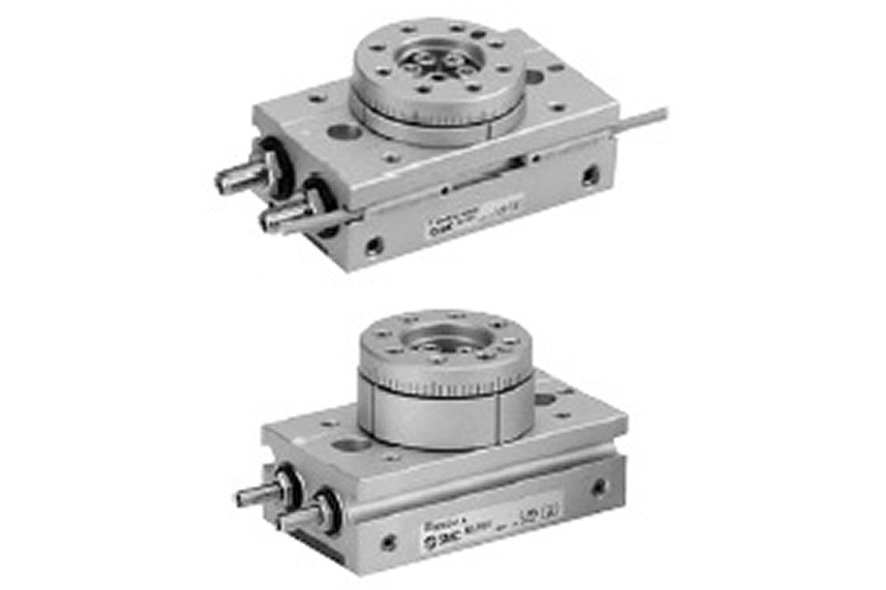
Off-square contact destroys seals fast — the dominant premature-failure mode. → Spec a self-aligning pivot mount or flat contact pad on rotary actuators, swinging loads, or any non-linear geometry. For delicate or finished-surface contact, add the cap / urethane bumper variant at the nose.
From the machine spec sheet → to the part number. Answer what you know — leave the rest blank — and send.
Most distributors sell one brand per product type. SPC's 60-brand portfolio means every Product Type page surfaces three real options matched to how your customer is buying today. Pick the tier; the quote desk handles the cross-reference.
Self-compensating is the OEM-designed-in absorber — no adjustment screw, no service drift, longer cycle life. If the customer's load and velocity will never change, this is the cleaner install. If anything is uncertain, quote adjustable instead.
Each industry below uses this product across the listed areas. Open an industry to see how it fits the rest of its system.
 Metalworking & Fabrication →
 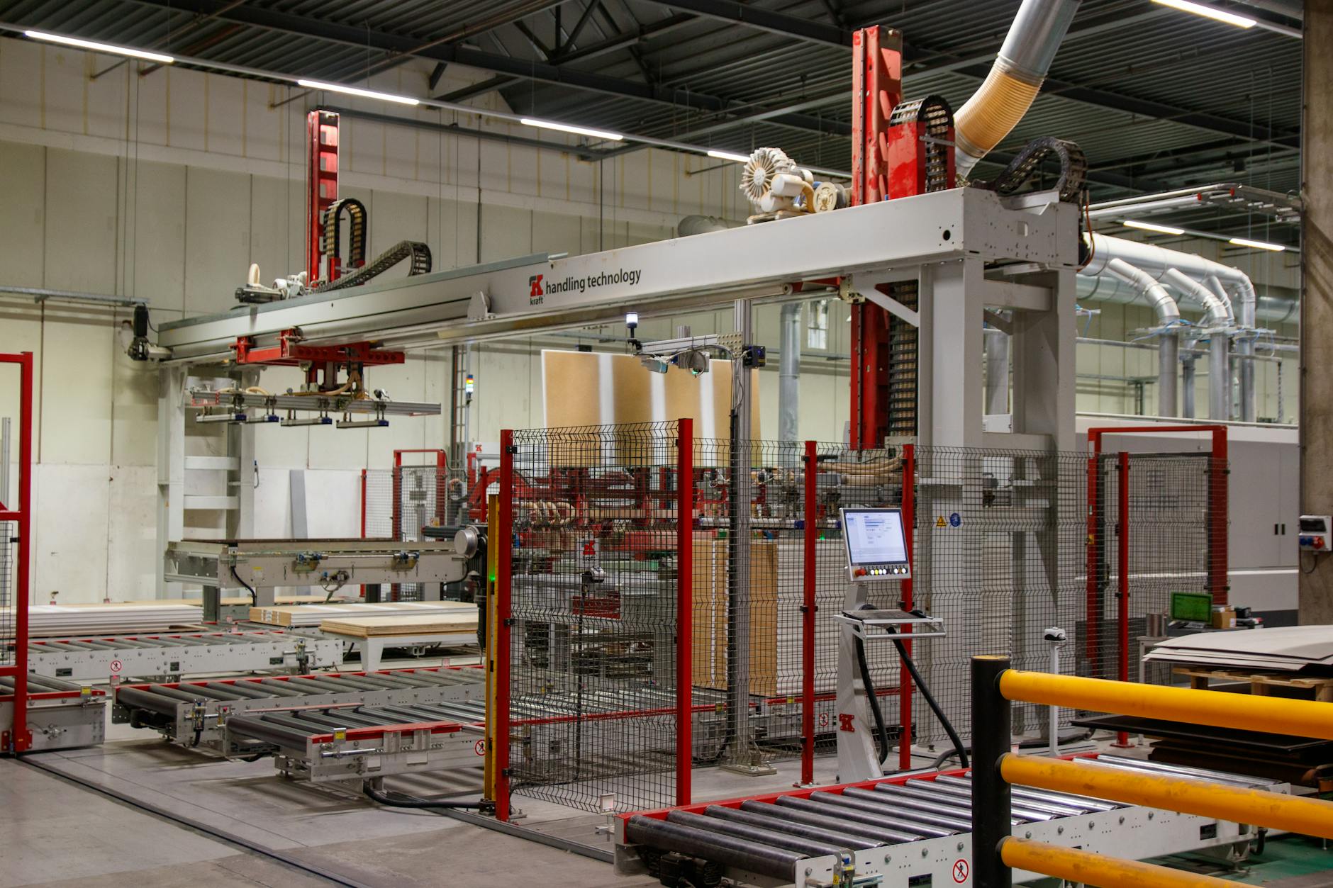 Material Handling & Conveyors →
 Also applies to OEM-designed-in machinery (SMC, Festo, Norgren, Bimba spec) · The largest install volume for self-compensating across SPC's territory. · High-cycle production lines (robotic, automated assembly, pick-and-place) · only viable choice · Robotic end-of-arm tooling (EOAT) · Indexing tables and rotary fixtures with stable operating points · high cycle counts reliably · Pneumatic-driven testing and inspection equipment · Replacement service across multi-machine fleets · steady annual replacement quantity that compounds over years
Every entry is a real product on this site — linked, not just named. Quote them on the same line item.
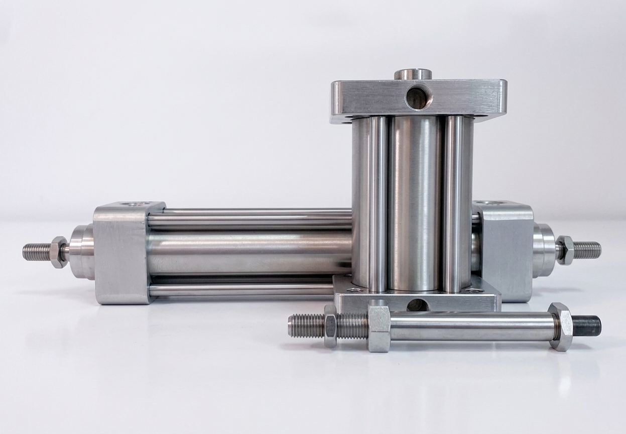
Service-route customers with installed self-comp fleets benefit from a cross-reference catalog on hand — SMC RB-Series, KOBA, and ACE cross at energy/velocity-class boundaries when lead times don't cooperate. Stock matched mounting hardware kits (nut + jam-nut + lock washer by thread size) alongside the absorbers so PM-route replacements aren't held up waiting on hardware.
Send us the application — a specialist routes you to the correct tier with a configured part. Lead-times and pricing returned within one business day.
—. We reply within one business day with pricing, lead-time, and configured parts.