DISTRIBUTOR-FIRST SUPPLY PARTNER · SINCE 1999 Live · Pneumatic Automation System
SPC Company
Pneumatic Automation / Motion Control / Speed & Flow Controls / Check Valve
01What it is

Check Valve

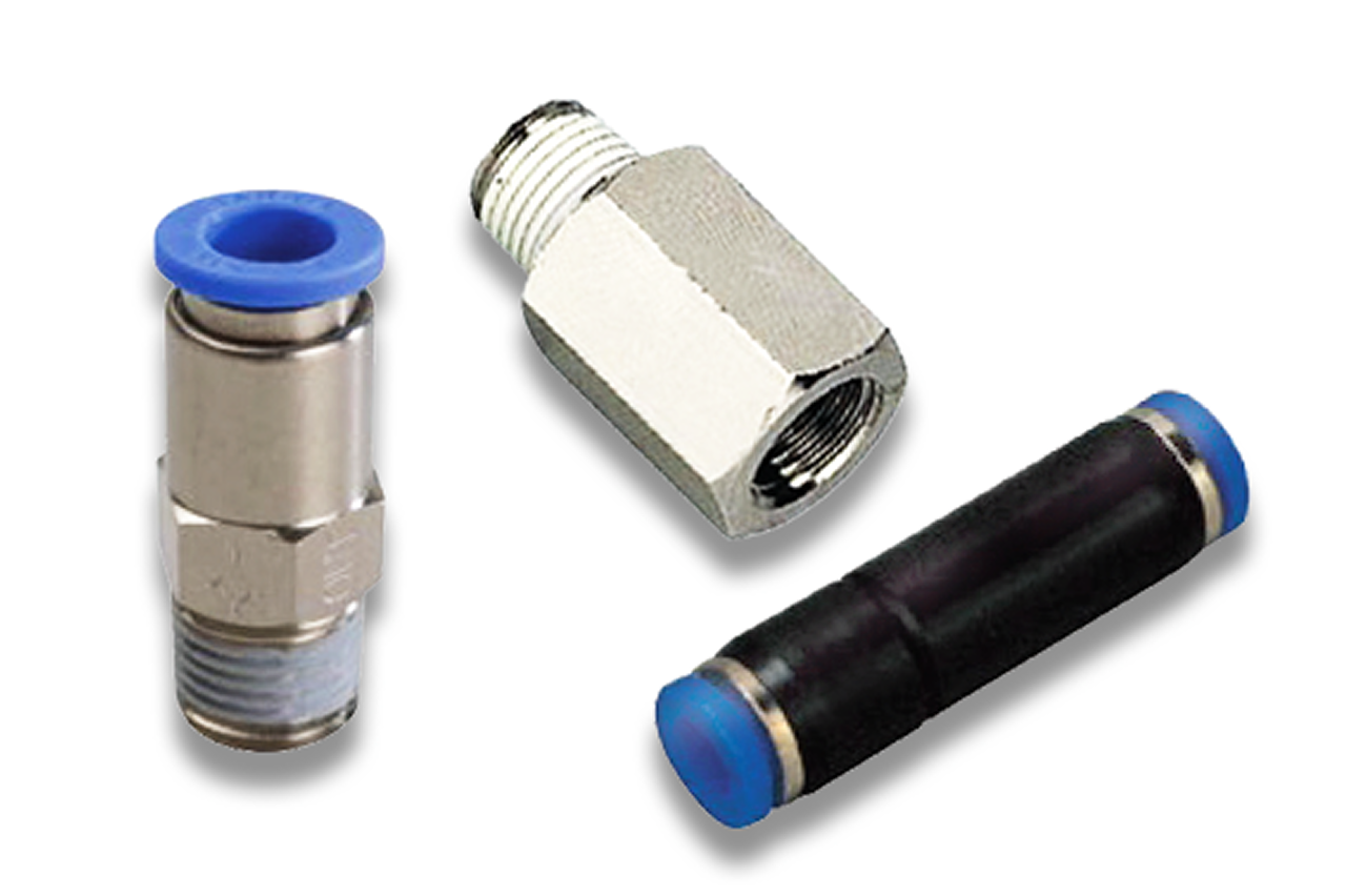
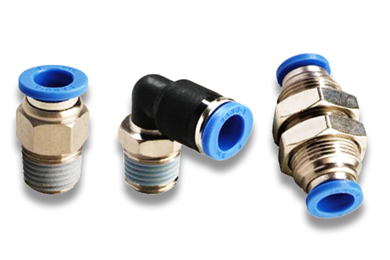
A check valve is an inline pneumatic component that lets air pass one way and seals against flow in the other. It is the cheapest, simplest line-protection device in the system — a few dollars, installs in seconds, and does three jobs no other component does cleanly: holds a load on a cylinder if supply pressure is lost (the pilot-operated variant traps air on both sides of the piston), prevents backflow that would feed pressure into a circuit that should be isolated, and builds simple pneumatic logic (paired with other checks, it forms shuttle and AND/OR functions without any electrical actuation). It installs in series with cylinders, valves, and shared-supply branches, and is sized to the same tube OD (the outside diameter of the air line) as the machine's push-to-connect fittings.

Real-world reference Representative check valve
Check Valve — representative product photo
02Why it's needed

Why this matters.

Tips and pointers on when the check valve is the right call — and when to spec something else. Scroll the strip →

01 · Key point
Holds the load on power loss.

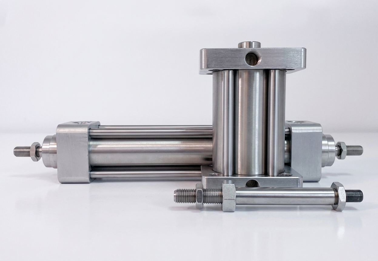
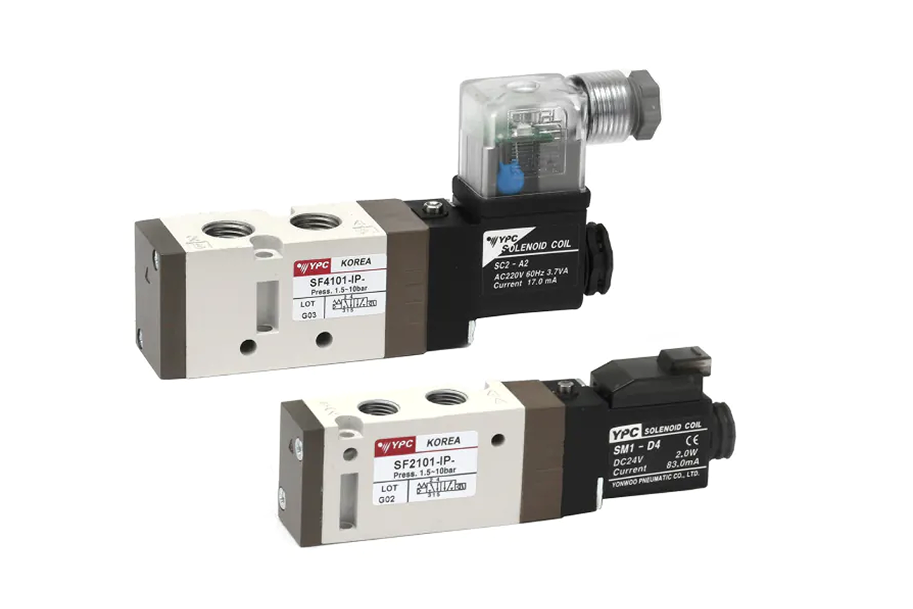
A spring-loaded poppet lifts above a low cracking pressure (1–5 PSI) and reseats the instant flow reverses or supply drops. Two pilot-operated checks at the cylinder ports trap air on both sides of the piston and lock the rod where it was — $20–50 load safety the DCV can't deliver.

02 · Key point
Prevents backflow on shared supply.

Two or more cylinders on the same line — a standard inline check in each branch keeps exhaust air from back-feeding into adjacent cylinders and causing unexpected motion. The fix for "strange motion" on packaging diverters and parallel reject stations.

03 · Key point
Builds pneumatic-only logic.

Two checks form a shuttle valve (OR logic); multiple checks plus shuttle valves build AND, OR, and priority functions with no electrical signal. Standard tool for hazardous-area equipment, portable rigs, and any station where electrical controls are absent.

04 · Pro tip
Pilot-op at the cylinder, not the supply.

For load holding the pilot-op check must trap the air actually holding the load — between the DCV and the cylinder chamber. Pilot line goes to the OPPOSITE cylinder chamber, not to supply. Two per double-acting cylinder; arrow points toward the actuator.

05 · Where not to use
Manual isolation for service.

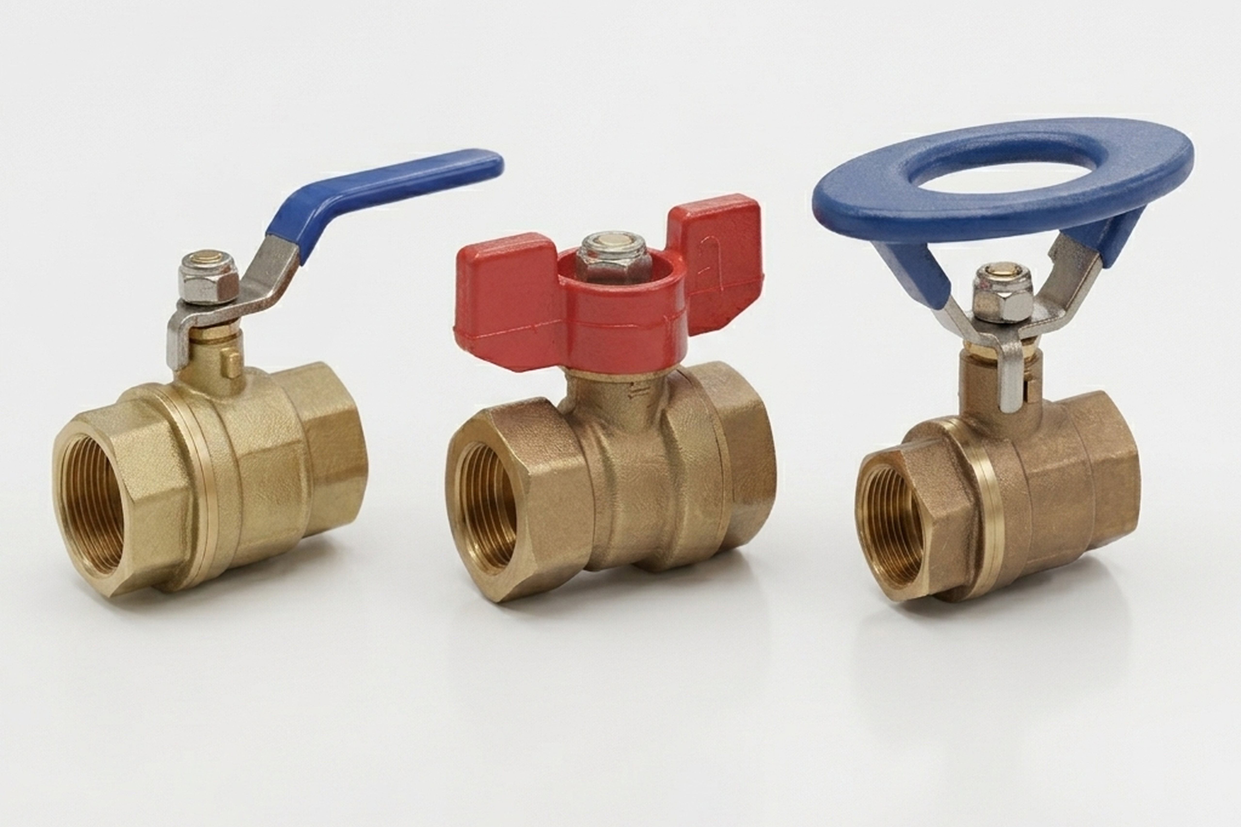
Checks are automatic and one-way — they don't isolate for lockout-tagout. → Re-spec to quarter-turn shutoff valve when the job is deliberate, manual, lockable isolation rather than backflow prevention. The two often pair in series on compressor discharge.

06 · Where not to use
Bidirectional throttling.

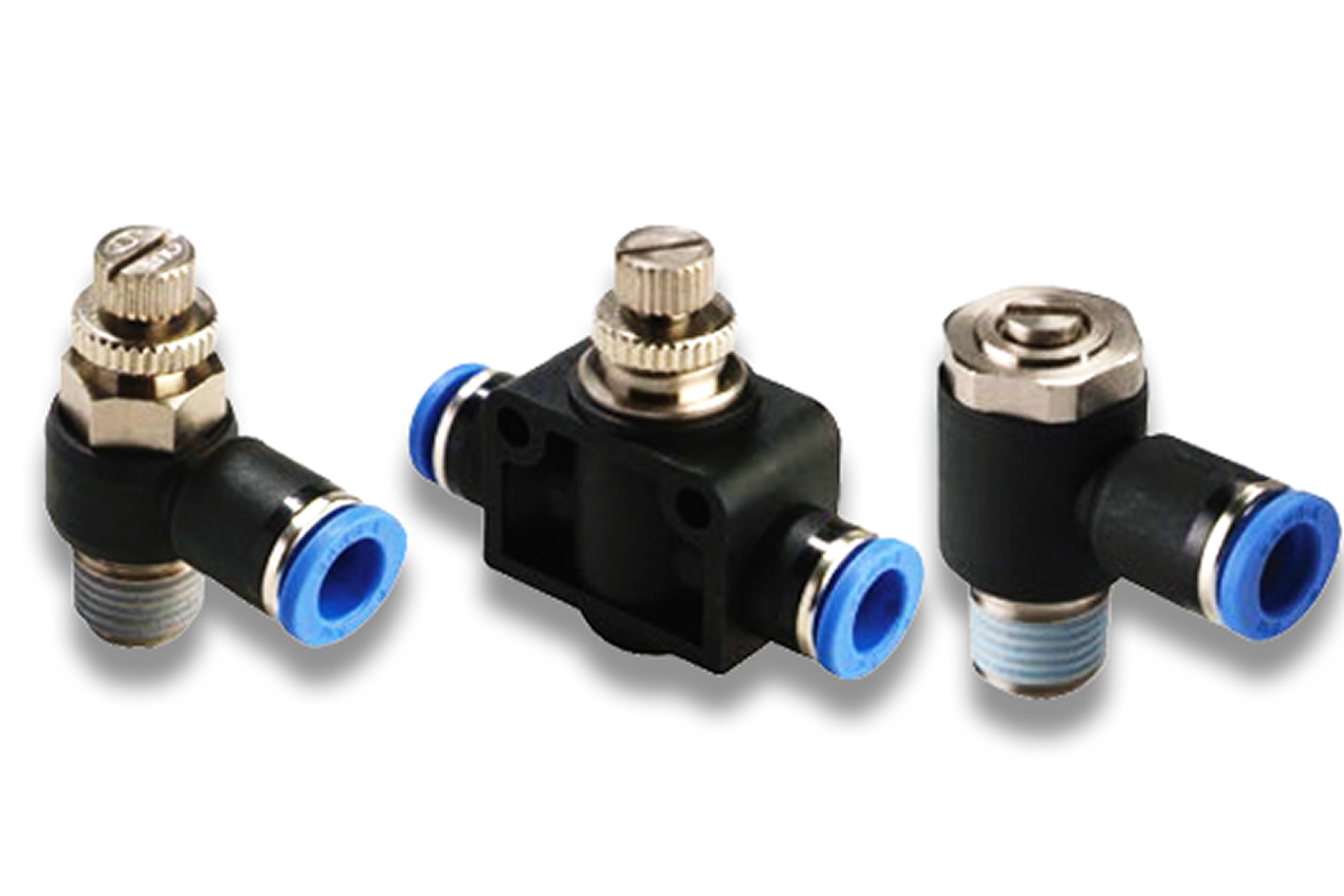
A check blocks reverse flow but does not throttle the forward direction. → Re-spec to flow control valve when the application needs tunable bidirectional metering for line balancing or pilot signal timing.

07 · Where not to use
Cylinder speed control.

A standalone check just opens or closes — it can't meter exhaust to smooth a cylinder's stroke. → Step up to speed controller at the cylinder port. The speed controller is an integral check plus needle valve in one body; the right call when one-direction throttling is wanted.

03Key selection criteria

What we need to spec it right.

From the machine spec sheet → to the part number. Answer what you know — leave the rest blank — and send.

01 · Input
The check valve's PTC end must match the machine's tube OD exactly. Mixing metric and inch is the most common at-install miss. Verbal "1/4 inch" can mean 1/4" NPT, 1/4" tube, or 1/4" BSPP — photo the existing fitting.
Metric tube OD: 4mm · 6mm · 8mm · 10mm · 12mm · 16mm · Inch: 1/4" · 3/8" · 1/2" · Threads: NPT · BSPP/G · BSPT
02 · Input
Driven by the job. Load holding at a cylinder port = pilot-operated (two per double-acting cylinder). Backflow prevention or pneumatic logic = standard inline (no pilot).
Standard inline (backflow / shuttle logic) · Pilot-operated (cylinder load holding — pilot to opposite chamber)
03 · Input
Read off the pneumatic schematic or trace the line. The body's directional arrow points toward the actuator or intended flow direction at install. Installing backwards is the #1 field mistake.
Free-flow toward actuator · Free-flow toward branch · Free-flow toward exhaust
04 · Input
Standard for general service is 1–5 PSI. Lower (~0.5 PSI) for low-pressure pilot signals where a higher crack would prevent the signal from opening the valve.
0.5 PSI (pilot signal) · 1 PSI · 3 PSI · 5 PSI (standard general service)
05 · Input
Confirm from the regulator setting on the machine drop. The check has a maximum-pressure rating — verify the system runs within it.
40–80 PSI · 80–125 PSI (typical plant) · 125–145 PSI · 150 PSI+ (verify rating)
06 · Input
Chosen by connection geometry — bushing for direct-thread into a component, straight union for inline tubing splice, elbow for tight spaces.
Bushing (direct-threaded) · Straight union (PTC both ends) · Male straight connector · Elbow
07 · Input
Count the one-way points on the build. Two pilot-op per double-acting load-holding cylinder; one standard inline per shared-supply branch. A 16-cylinder load-holding machine typically lands at 20–50 check valves. Pilot-op and standard inline are different SKUs — separate lines.
1–10 pcs · 20–50 pcs (machine build with load holding) · 50 / 100-ct case (plant infrastructure refresh)

Need different sizes, colors, or quantities? Fill the form, add to quote, then fill again — each click is one quote line.

05How to sell this  ·  distributor talk track

The tier conversation closes the deal. The cross-reference catalog wins the next one.

Ask whether the cylinder holds a load. If yes, two pilot-operated check valves go on every cylinder quote — and the customer almost always asks why the original integrator didn't do this.
The SPC difference · how distributors actually buy

The 30-second positioning

Three jobs drive the quote. Load holding = pilot-operated check at each cylinder port, two per cylinder. Backflow prevention = standard inline check in each branch of a shared-supply circuit. Pneumatic logic = standard checks plus shuttle valves built from check pairs, per the circuit schematic.

Tier: Economical tier is the value default — full 4mm-16mm metric and 1/4"-1/2" inch coverage, full body-style coverage, competitive pricing on high-volume sizes. Industry Leader tier for matched-vendor builds where the rest of the pneumatic train is single-brand.

Quote errors are narrow. Tube OD and thread spec (NPT in North America, BSPP/G in European, BSPT in some Asian) — pictures of the existing fittings remove all ambiguity. A 16-cylinder machine with load-holding throughout needs 32 pilot-op checks at cylinder ports plus 4-8 standard inline checks in supply branches; 20-50 check valves per machine is typical, priced in box quantities of 50 or 100 at the manufacturer's break point.

Customer cue → talk move

"Cylinder holds a load — what if air goes out?"
Pilot-op checks, two per cylinder, at the cylinder ports. Walk the failure-mode logic.
"Need a one-way fitting"
Standard inline check. Confirm flow direction at quote time.
"Shared supply with two cylinders, strange motion"
Backflow through the shared supply. Check valve in each branch immediately downstream of the tee.
"Building pneumatic-only logic for a remote station"
Standard inline checks plus shuttle valves (check pairs). Trigger and sequence logic without any electrical signal.
"Replacing old check valves"
Match tube OD and thread spec. Most older checks cross-reference to current Economical or Industry Leader tier parts without changing tubing.
"Cylinder drops when line shuts down for the night"
Pilot-op checks at cylinder ports. The directional valve alone does not hold position once supply is lost.
06Where it's used

Industries served.

Each industry below uses this product across the listed areas. Open an industry to see how it fits the rest of its system.

Also applies to Load-holding on lift, clamp, and indexing cylinders · Shared-supply circuits on multi-cylinder machines · Pneumatic-only sequential logic on hazardous-area equipment · Vacuum hold-on with check-valve backup · Pressure-balanced cylinder circuits · Aftermarket retrofit for safety improvement · Compressor discharge backflow protection

09Install · 6 critical steps

The things that matter on the first install.

Step 01
Confirm flow direction with the arrow on the body
Every check valve has a directional flow arrow molded or stamped on the body. Installing backwards is the #1 field mistake — the valve won't pass flow, the cylinder won't move, and the diagnosis will burn an hour. Arrow points toward the actuator (or toward the intended flow direction in a branch line).
Step 02
Pilot-op checks go at the cylinder ports, not in the supply line
For load holding, the pilot-op check must trap the air actually holding the load — between the directional valve and the cylinder chamber. In the supply line it traps supply pressure but not chamber pressure; the cylinder still bleeds and drops.
Step 03
Plumb the pilot line to the OPPOSITE cylinder chamber
When the directional valve commands the cylinder to move, pilot pressure releases the check on the opposite port and lets exhaust flow. Wrong pilot plumbing means the check never releases and the cylinder can't move. Most pilot-op checks label the pilot connection "PILOT" or "X" — connect per the manufacturer's diagram.
Step 04
Thread sealant by thread type
NPT = 2-3 wraps of PTFE tape in the direction of engagement. BSPP/G = O-ring or bonded washer at the face, NO sealant on threads. Mixing methods causes either thread leaks (BSPP with tape, no face seal) or face leaks (NPT with no sealant).
Step 05
Bench-test before final assembly
10-20 PSI shop air on a regulator: forward should pass with a click as the poppet opens; reverse should stop immediately. Catches the rare manufacturing defect (debris in the seat, broken spring) before the valve is built into hard-to-service plumbing.
Step 06
For logic circuits, sketch before plumbing
Check-valve logic gets to spaghetti fast. Sketch the schematic, label each check and each tubing run, verify the logic on paper. Field-debugging unlabeled pneumatic logic is harder than wiring-debugging the electrical equivalent.
10Troubleshoot · top failures

Most returns trace to one of these causes.

Symptom
Most likely cause
Fix
Cylinder won't move; supply pressure OK, directional valve shifting
Check installed backwards (most common after new install), OR pilot-op check not releasing (pilot line wrong or disconnected), OR debris jamming the poppet.
Trace flow path; verify each arrow. For pilot-op, verify pilot line goes to the opposite cylinder chamber. If both correct, bench-test the check.
Cylinder slowly drifts down over hours/days, valves de-energized
Pilot-op check seats leaking (small particulate damage), OR cylinder piston seals bypassing, OR 5/3 closed-center spool seals leaking.
Isolate the leak path. With supply isolated and cylinder loaded, listen at the directional valve's exhaust — hissing = directional valve leak. Silent but cylinder still drops = check seals OR cylinder seals. Swap checks first (cheaper than a cylinder rebuild); if drop persists, the cylinder is the cause.
Audible chatter or pulsing during flow
Valve undersized for flow rate (poppet partially open, oscillating in the stream), OR cracking pressure too high for the application.
Confirm Cv against actual flow demand. Step up one size if at or near max. If sizing is right, swap to a lower cracking-pressure variant.
Continuous leak when valve should be sealed
Debris in the seat (#1 cause — particulate from a degraded upstream coalescing filter, scale from a corroded pipe, install-time debris not flushed), OR elastomer seat chemical damage, OR broken spring.
Remove and inspect the seat. Light contamination can reverse-flush with shop air; severe damage = replacement. If recurring, service the upstream coalescing filter.
Pilot-op check releases when it should hold (cylinder drops with directional valve centered)
Pilot internal seal leaking, OR pilot line plumbed to supply instead of opposite chamber, OR 5/3 center leaking and pressurizing the pilot line.
Verify pilot plumbing per the diagram. Pressure-test the pilot connection with cylinder isolated — pilot pressure present when it shouldn't be = the source is the leak. Replace the pilot-op check if its pilot seal is leaking; service the directional valve if its 5/3 center is leaking.

Get the right check valve on quote in 24 hours.

Send us the application — a specialist routes you to the correct tier with a configured part. Lead-times and pricing returned within one business day.

Request a quote