DISTRIBUTOR-FIRST SUPPLY PARTNER · SINCE 1999 Live · Pneumatic Automation System
SPC Company
Pneumatic Automation / Motion Control / Speed & Flow Controls / Flow Control Valve
Layer 05 · Motion Control Emerging · Sang-A
01What it is

Flow Control Valve

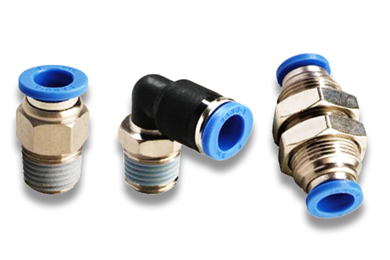
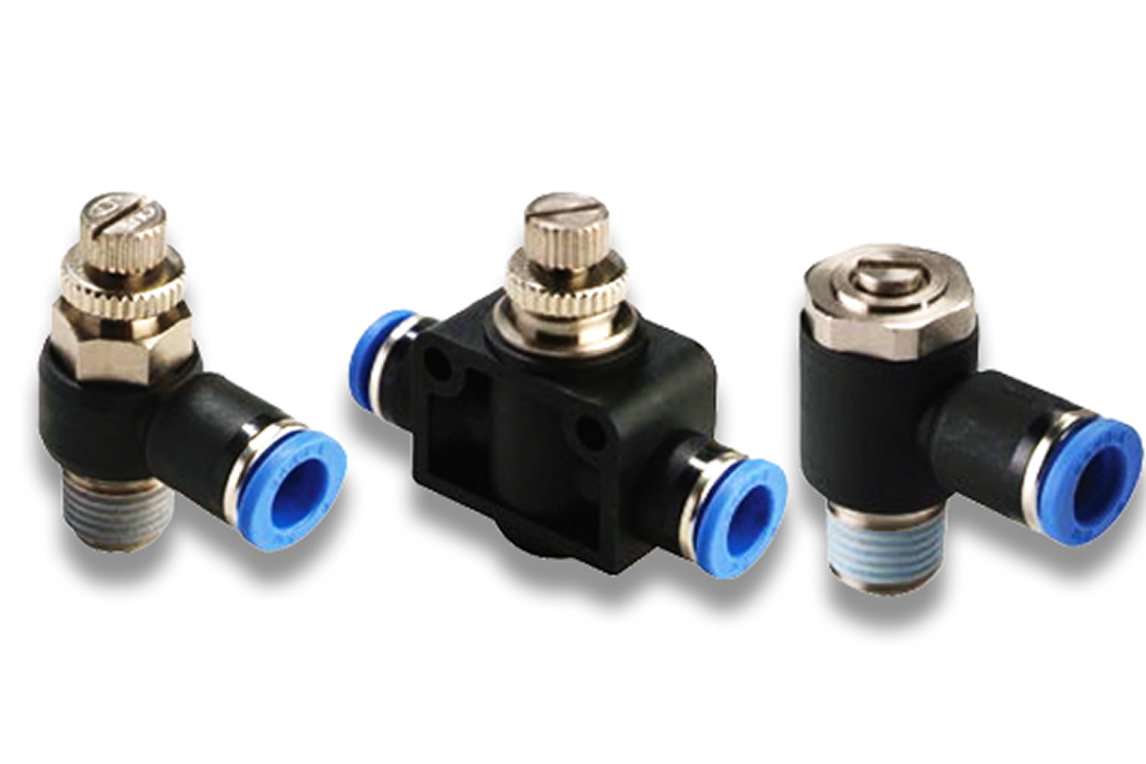
A flow control valve is an inline needle valve that meters air flow in a pneumatic line in BOTH directions equally. Turning the knurled knob advances or retracts a metering needle, narrowing or widening the flow path. Unlike a speed controller it has no integral check valve — that single difference is the entire spec conversation. The flow control is the right tool for line-level jobs: balancing a branch so two parallel circuits draw their fair share, slowing a pilot signal so a sequenced motion doesn't fire too early, trimming the feed to a sub-circuit that doesn't need the full system flow. It is the WRONG tool for cylinder speed (which needs one-direction throttling — see speed-controller). It installs in series in the line and is sized to the same tube OD as the machine's push-to-connect fittings.

Real-world reference Representative flow control valve
Flow Control Valve — representative product photo
02Why it's needed

Why this matters.

Tips and pointers on when the flow control valve is the right call — and when to spec something else. Scroll the strip →

01 · Key point
In-line adjustable restriction.

A knurled-knob needle valve in series with the line — open for more flow, close for less, change is immediate. The most-used adjustment device in a pneumatic shop after the regulator. Tunes flow without re-piping.

02 · Key point
No integral check — meters both ways.

That single difference from a speed controller is the entire spec conversation. The flow control meters BOTH directions equally — right for line balancing, pilot signal timing, and sub-circuit trimming; wrong for cylinder speed.

03 · Key point
Four jobs cover the catalog.

Line balancing on parallel circuits. Pilot signal timing for soft-start or sequenced motions. Sub-circuit trimming on shared supplies. General line restriction on test stands. A few per machine, scattered across the schematic.

04 · Pro tip
Size against actual flow, not tube OD.

Operational flow should fall in the middle of the needle's usable travel. Oversized = "barely cracked" — small adjustments produce huge flow changes, fine-tuning impossible. Undersized = full open and still restricting. After tuning, engage the lock and paint-pen the position so drift is visible.

05 · Where not to use
Cylinder speed control.

About a third of "I need a flow control" calls are speed-controller calls in disguise. Bidirectional metering doubles cylinder cycle time and creates jerky load-dependent motion. → Re-spec to speed controller at the cylinder port — integral check delivers one-direction throttling, which is what cylinder speed actually needs.

06 · Where not to use
One-way backflow blocking.

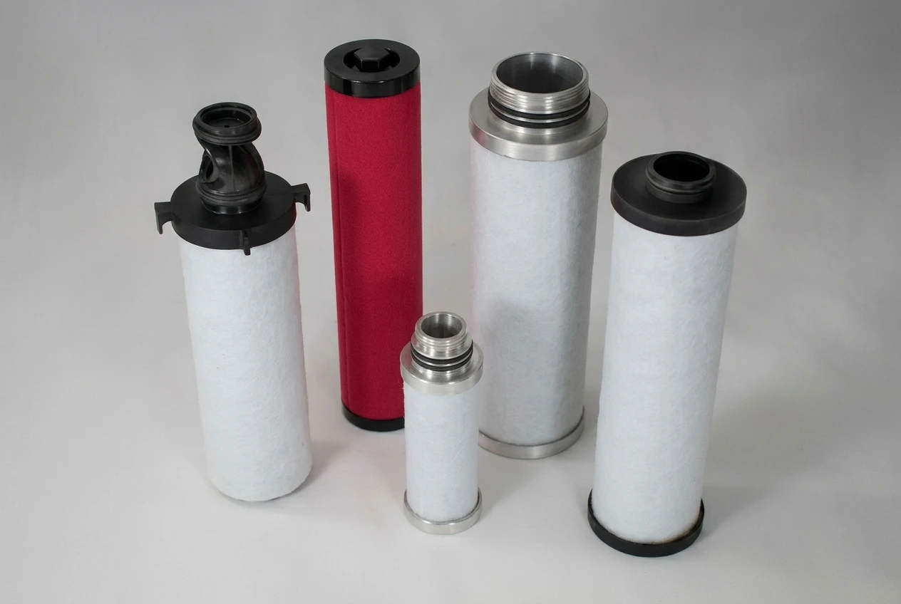
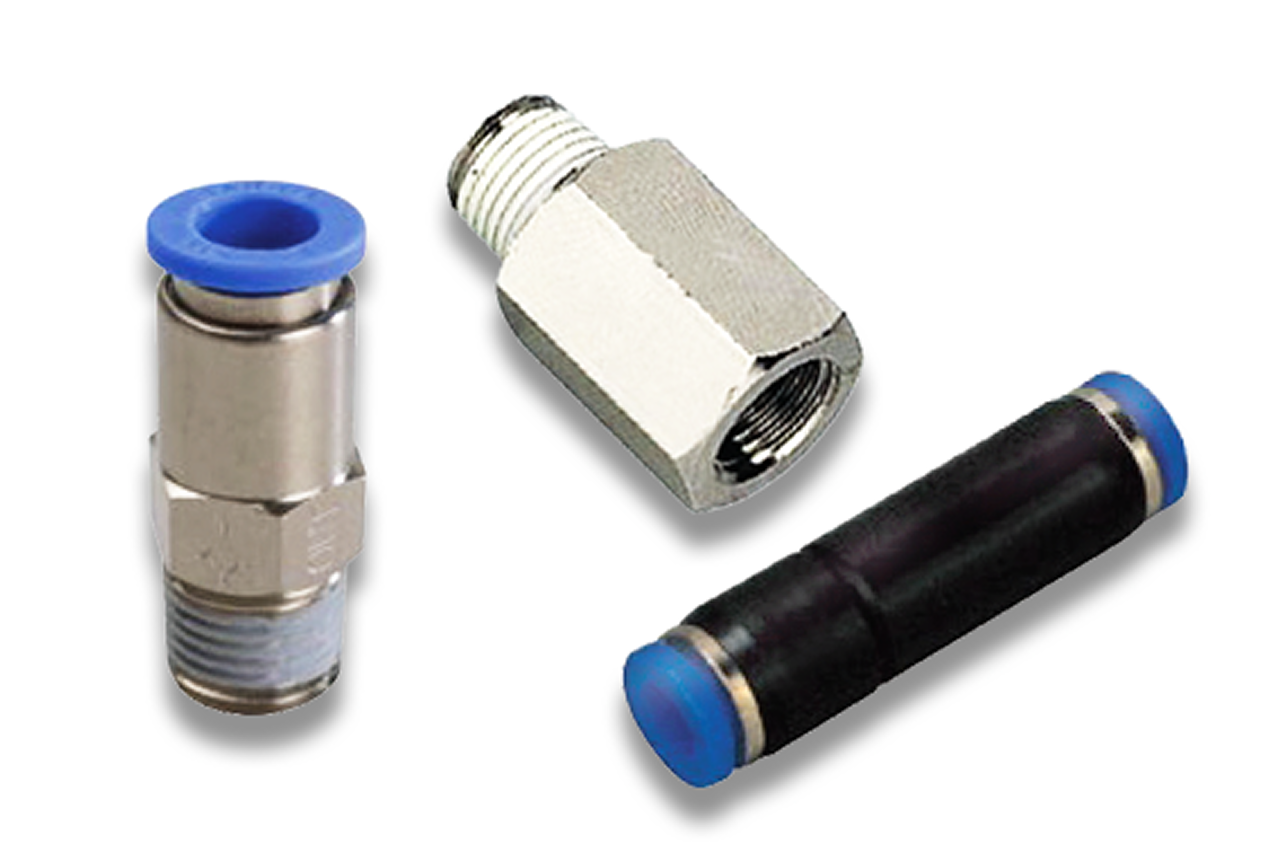
A flow control throttles but never blocks reverse flow. → Re-spec to check valve when the job is full one-way blocking — load holding on a cylinder, backflow prevention on a shared supply, or pneumatic-only logic.

07 · Where not to use
Manual isolation for service.

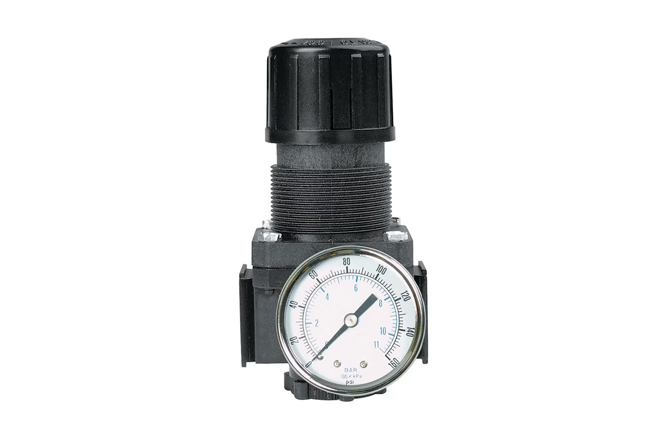
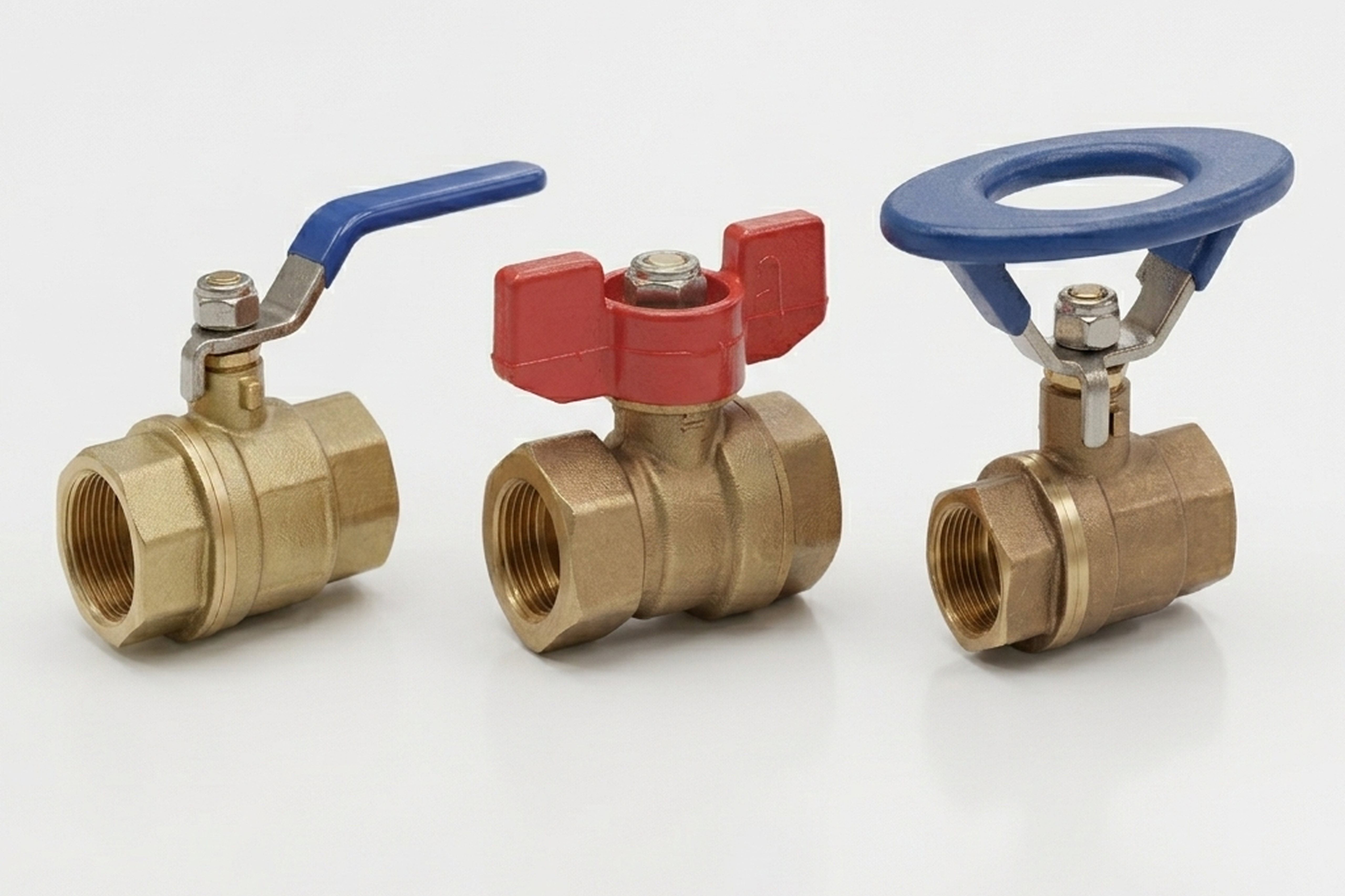
A flow control is always at least partly open — it can't be locked off for OSHA lockout-tagout. → Re-spec to quarter-turn shutoff valve when the job is manual full isolation. Different mechanism, different job.

03Key selection criteria

What we need to spec it right.

From the machine spec sheet → to the part number. Answer what you know — leave the rest blank — and send.

01 · Input
The flow control's PTC end must match the machine's tube OD exactly. Photo of the existing fitting removes thread ambiguity.
Metric tube OD: 4mm · 6mm · 8mm · 10mm · 12mm · 16mm · Inch: 1/4" · 3/8" · 1/2" · Threads: NPT · BSPP/G · BSPT
02 · Input
About a third of "flow control" RFQs are speed-controller RFQs in disguise — verify the throttle lives in the LINE, not at a cylinder port, before quoting.
Line balancing (parallel branches) · Pilot signal timing (sequenced motion delay) · Sub-circuit feed trim · Test stand / general restriction · NOT cylinder speed → re-spec to speed controller
03 · Input
From the line's actual flow demand at operation, not the tube size. Sizes the valve so operational flow falls in the middle of the needle's usable travel. Oversized = "barely cracked" makes fine-tuning impossible.
<5 SCFM (pilot / signal) · 5–20 SCFM (small sub-circuit) · 20–60 SCFM (general line) · 60+ SCFM (main branch)
04 · Input
Confirm from the regulator setting on the machine drop. The valve has a maximum-pressure rating — verify the system runs within it.
40–80 PSI · 80–125 PSI (typical plant) · 125–145 PSI · 150 PSI+ (verify rating)
05 · Input
Chosen by connection geometry and where the adjustment knob needs to sit. Lock-ring or set-screw on every variant prevents drift after tuning.
Inline straight (general) · Elbow (tight spaces) · Panel-mount (behind-panel adjustment) · Bushing (direct-thread)
06 · Input
Count line points needing adjustable flow on the build — usually a few per machine, scattered across the schematic. Bulk-replacement refreshes go into 25- or 50-count cases.
1–5 pcs (single-machine scatter) · 10–25 pcs (multi-line tuning) · 25 / 50-ct case (maintenance refresh)

Need different sizes, colors, or quantities? Fill the form, add to quote, then fill again — each click is one quote line.

04Choose your solution tier  ·  core differentiator

Whatever your lever — spec, value, or price — SPC has the right brand.

Most distributors sell one brand per product type. SPC's 60-brand portfolio means every Product Type page surfaces three real options matched to how your customer is buying today. Pick the tier; the quote desk handles the cross-reference.

05How to sell this  ·  distributor talk track

The tier conversation closes the deal. The cross-reference catalog wins the next one.

A third of flow-control RFQs are really speed-controller RFQs in disguise. Ask whether it's for a cylinder. If yes, pivot the quote — the customer wanted one-direction metering and used the more generic term.
The SPC difference · how distributors actually buy

The 30-second positioning

Four application contexts drive the quote. Line balancing on a branched circuit = inline flow control in each branch. Pilot signal throttling = flow control in the pilot tubing to delay a downstream valve's shift. Sub-circuit trimming reduces flow to a low-demand sub-circuit. General line restriction on a test stand or temporary setup uses it as a tunable orifice.

Tier: Economical tier is the value default — commodity functional fitting category, full size + thread coverage. Industry Leader tier for matched-vendor installations where the rest of the pneumatic train is single-brand.

Spec errors are narrow. Tube OD and thread type (NPT in North America, BSPP/G in European) — pictures of the existing line remove all ambiguity. Sizing against the actual flow demand is the second move: operational flow should fall in the middle of the needle's usable travel. Quoting in small quantities is normal — a few per machine, scattered across the schematic. Bulk-replacement refreshes go into 25- or 50-count cases.

The consultative move — flow control or speed controller? About a third of "I need a flow control" calls are actually speed-controller calls. Pivot the quote and explain: integral check valve gives one-direction metering, which is what cylinder speed actually needs. Customers appreciate the spec-correction; quoting the wrong product because the customer used a loose term creates field problems later.

Customer cue → talk move

"Need a flow control for a cylinder"
Almost certainly wants a speed controller. Pivot and explain. If the customer insists after the explanation, quote as requested with a note documenting the conversation.
"Two parallel circuits on the same supply, one running faster"
Inline flow control in the faster branch. Trim until balanced. Cheap fix.
"Pilot-operated valve fires too early in the sequence"
Inline flow control in the pilot line, set to slow the pilot rise. Delays the downstream actuation by a tunable amount.
"Slow an air tool without changing the regulator"
Inline flow control in the tool supply line. Tool runs at full system pressure but with restricted flow — different feel than pressure reduction.
"Existing flow control replaced, line is acting wrong"
Almost always the replacement was a speed controller (with check) and the original was a flow control (no check), or vice versa. Verify part numbers.
"Bulk replacement on a maintenance refresh"
Box quantities. Flow controls are cheap and customers usually replace all of them on a major service.
06Where it's used

Industries served.

Each industry below uses this product across the listed areas. Open an industry to see how it fits the rest of its system.

Also applies to Line balancing on multi-branch pneumatic circuits · Pilot signal timing on sequenced machines · Sub-circuit feed restriction · Pneumatic logic and timing circuits · Test stand flow tuning · Tool-line throttling

09Install · 5 critical steps

The things that matter on the first install.

Step 02
Mount with the adjustment accessible
The flow control is meant to be adjusted in service. A tight cabinet location or behind other equipment defeats the adjustability. Locate where a tech can reach the knurled knob with the line under pressure for live tuning. Panel-mount variants exist for behind-panel adjustment.
Step 03
Thread sealant by thread type
Same as check valves — NPT needs sealant on the male thread (PTFE tape, 2-3 wraps in the direction of engagement). BSPP seals at the face with an O-ring or bonded washer — no sealant on threads. Mixing methods causes leaks at the wrong location.
Step 04
Set the needle to roughly mid-travel before pressurizing
Most flow controls ship fully open or fully closed depending on the manufacturer. Mid-travel at first pressurization gives a known starting point and prevents zero-flow or full-flow surprises.
Step 05
Tune with the line running, not static
Flow controls behave differently under flow vs. at rest. Tune with the actual application running — observe the downstream behavior and adjust the needle in small increments. Static adjustments rarely land on first try.
Step 06
Lock the setting against unintended adjustment
Most knurled-knob flow controls include a locking ring or set screw that prevents the knob from moving after the setting is dialed in. Engage the lock after tuning is complete. Without the lock, the next service tech (or vibration, or a snagged hose) will move the setting and re-create the problem the valve was installed to solve. Paint-pen the final position so drift is visible.
10Troubleshoot · top failures

Most returns trace to one of these causes.

Symptom
Most likely cause
Fix
Adjusting the valve has little visible effect on the downstream behavior
Valve oversized for the application (needle is at "barely cracked" for normal operation; further closing has little effect until very near closed), OR the valve is installed in a path that doesn't actually control the observed behavior, OR there's a parallel path bypassing the flow control.
Flow-test with the valve fully closed — should completely stop the downstream behavior. If not, the valve isn't in the path or there's a parallel route. If it's in the right path but adjustment range is too coarse, swap to a smaller-Cv flow control where the operational flow falls in the middle of the needle's usable range.
Valve fully open, downstream still restricted
Valve undersized for actual flow demand, OR another restriction (kinked hose, undersized fitting, plugged muffler) downstream.
Bypass the flow control with a straight union and observe whether the restriction clears. If it clears, quote a larger valve. If it persists, find the downstream choke point.
Setting drifts over time
Vibration unlocking the adjustment, OR the locking ring or set screw was never engaged after tuning, OR a service tech adjusted the valve and didn't document the change.
Verify the lock is engaged. Document the setting with a paint-pen mark on the knurled knob and the body — any future adjustment is visible at a glance.
Audible hiss or chatter at certain settings
At very low flow rates the needle and seat can chatter from flow-induced oscillation. Rarely damaging but annoying — indicates operation at the edge of the valve's useful range.
Re-size to a smaller Cv so the operating point sits in the middle of the needle's range, or accept the chatter if the application tolerates it.
Leak at the body or threads
Thread sealant applied incorrectly (NPT without sealant, BSPP with tape on threads instead of face seal), OR over-torqued and cracked the body, OR damaged O-rings or face seal.
Re-make the joint with the correct sealing method for the thread type. If the body cracked from over-torque, replace.

Get the right flow control valve on quote in 24 hours.

Send us the application — a specialist routes you to the correct tier with a configured part. Lead-times and pricing returned within one business day.

Request a quote