What it is
The machine's eyes — position, pressure, vacuum
Three sensors that each watch one physical variable and stream a discrete or analog signal back, closing the control loop to the PLC.
Three feedback questions, one machine. Did the cylinder reach position, is the pressure where it should be, and did the vacuum gripper actually grab? This page walks the spec from "the machine needs to confirm what it just did" to the right sensor on the quote — what each one watches, where it mounts, and what it streams back to the PLC.
Tap any type to jump to its page. The Decision Guide further down asks three questions that funnel the spec to one of these.
Three sensors that each watch one physical variable and stream a discrete or analog signal back, closing the control loop to the PLC.
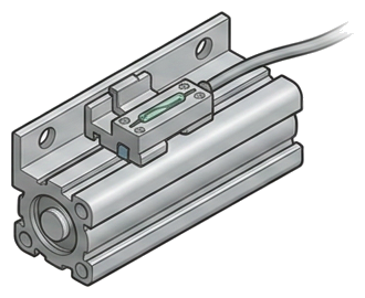
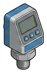
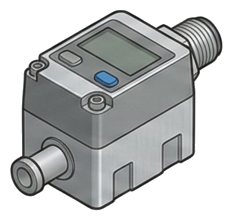
Rod position → cylinder-position sensor. Supply or filter → pressure sensor. Suction grip → vacuum switch. The three don't substitute.
Without feedback the controller is guessing — a missed stroke or dropped part propagates downstream as scrap or a crash.
PNP vs NPN, switched vs analog vs IO-Link, supply voltage — a mismatch is the #1 cause of a dead sensor at commissioning. Pull the card spec first.
Distributor-facing reading. The trade-off column is the one that closes the loop — every type buys something and gives something up. Knowing what each type costs you is how the right one gets on the quote without a callback.
This isn't a tier comparison — the three rows watch three different physical variables (rod position, line pressure, circuit vacuum), so there's no substituting one for another. Read it as "what each device watches, where it mounts, and what it streams to the PLC." What they share is the one rule that breaks installs: the output type (PNP vs. NPN, switched vs. analog vs. IO-Link, voltage) has to match the PLC input card — confirm that before quoting any of the three.
Draw a line from the customer's answer at the top to the type name at the bottom. This is the page distributors screenshot and send to a customer the day before a quote call — so the customer comes prepared with the answers, and the call is about the brand and the budget, not the basics.
The root question — what physical variable does the machine need to confirm — picks the device cleanly; the three don't substitute for one another. The call that actually breaks at commissioning is electrical, and it's the same for all three: match the output type to the PLC input card (PNP vs. NPN, switched vs. analog vs. IO-Link, and the supply voltage). Pull the input card spec before quoting any sensor on this page.
If the customer answers most of these at the first call, the second call is the quote. If they can't answer any, the sensors & switches are rarely the only spec gap — flag it and push for a site walk.
Everything upstream of this layer commands motion; nothing upstream knows whether the motion succeeded. Sensing & Feedback is the layer that turns an open-loop pneumatic machine into a controlled one. A directional valve fires and a cylinder is supposed to extend — but the only way the PLC knows the rod actually reached end-of-stroke, that supply pressure is in spec, or that a vacuum gripper has truly latched onto the part, is a sensor reporting it back. Without that feedback the controller is guessing, cycle timing is open-loop, and a missed stroke or a dropped part propagates downstream as scrap or a crash. This layer is where the air-powered side of the machine meets the electrical control system: magnetic cylinder-position sensors, pressure switches, and vacuum switches each watch one physical variable and stream a discrete or analog signal to the PLC. Get this layer wrong and the machine runs blind — it cycles on a timer and hopes; get it right and every motion is confirmed, every fault is caught at the station that caused it, and the controller has the cycle and diagnostic data to run closed-loop.
The machine-feedback layer — magnetic cylinder-position sensors, pressure switches, and vacuum switches that confirm motion happened and stream cycle and diagnostic data to the PLC. The upgrade that turns an open-loop pneumatic machine into a monitored one.
The Control & Valving layer the feedback loop closes around — the directional valves command the motion; the cylinder-position sensors confirm it landed. The valve fires, the sensor reports back.
→The End-Use actuators the position sensors clamp to. The magnet on the cylinder piston is what the sensor detects; spec the sensor mounting style to the cylinder profile on the same quote.
→Tell us the end-use, the rough flow, and what climate the unit would sit in. We'll come back with a configured quote — the right type, the right tier, and the upstream gear the warranty assumes.
—. We reply within one business day with pricing, lead-time, and configured parts.